Ultrasonic flow measuring device

A flow measurement device, ultrasonic technology, applied in the direction of measuring device, measuring flow/mass flow, liquid/fluid solid measurement, etc., can solve problems such as inability to satisfy long straight pipe sections, fluid velocity distribution distortion, and velocity distribution asymmetry, etc. To achieve the effect of improving user experience, improving sealing performance and improving utilization rate

Pending Publication Date: 2019-06-04
CHARODEN IND TECH (SHANGHAI) CO LTD
View PDF0 Cites 2 Cited by
  • Summary
  • Abstract
  • Description
  • Claims
  • Application Information

AI Technical Summary

Problems solved by technology

[0002] At present, in the related technology, the pipeline is connected with the ultrasonic flowmeter. Due to the existence of flow resistance parts such as elbows and valves, the fluid velocity distribution in the pipeline is distorted and the velocity distribution is asymmetrical. Therefore, only the upstream of the ultrasonic flowmeter can be guaranteed. Only with a long enough straight pipe section can the measurement accuracy be met. In general, in field applications, the requirement for a long enough straight pipe section cannot be met, which limits the application range of the ultrasonic flowmeter. Therefore, in order to meet the measurement accuracy of the ultrasonic flowmeter Under the premise of reducing the length of the straight pipe required by the ultrasonic flowmeter, it is very necessary

Method used


Image

  • Ultrasonic flow measuring device
  • Ultrasonic flow measuring device
  • Ultrasonic flow measuring device

Examples


Embodiment Construction

[0030] In order to understand the above-mentioned purpose, features and advantages of the present invention more clearly, the present invention will be further described in detail below in conjunction with the accompanying drawings and specific embodiments. It should be noted that, in the case of no conflict, the embodiments of the present application and the features in the embodiments can be combined with each other.

[0031] In the following description, many specific details are set forth in order to fully understand the present invention. However, the present invention can also be implemented in other ways different from those described here. Therefore, the protection scope of the present invention is not limited by the specific details disclosed below. EXAMPLE LIMITATIONS.

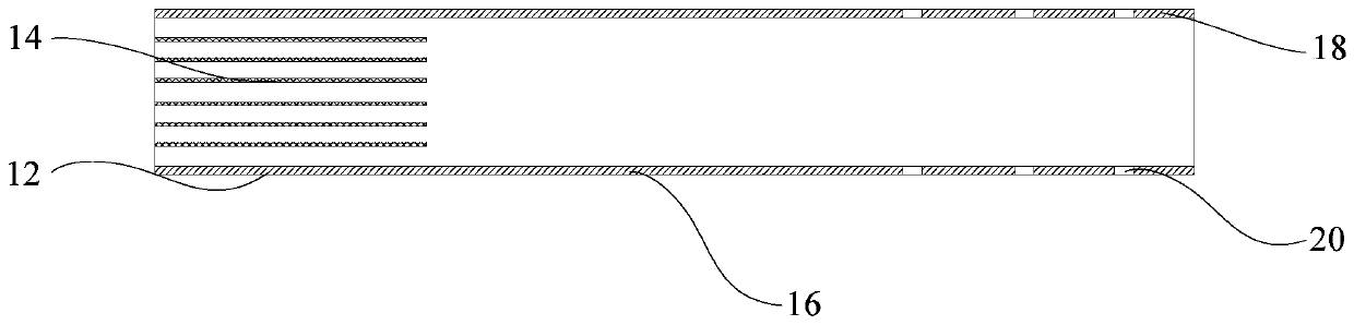
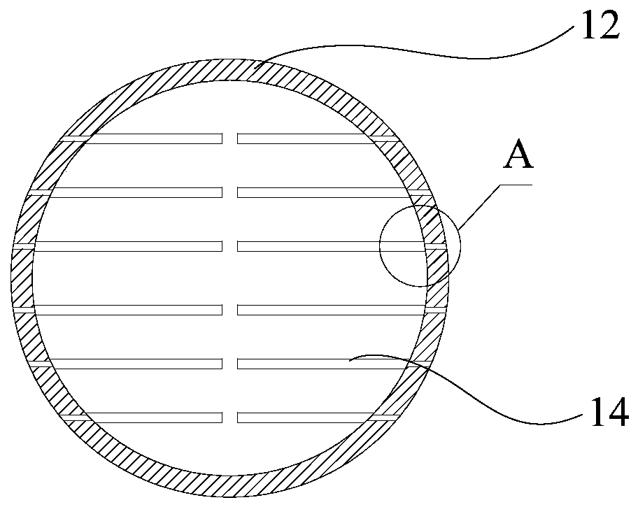
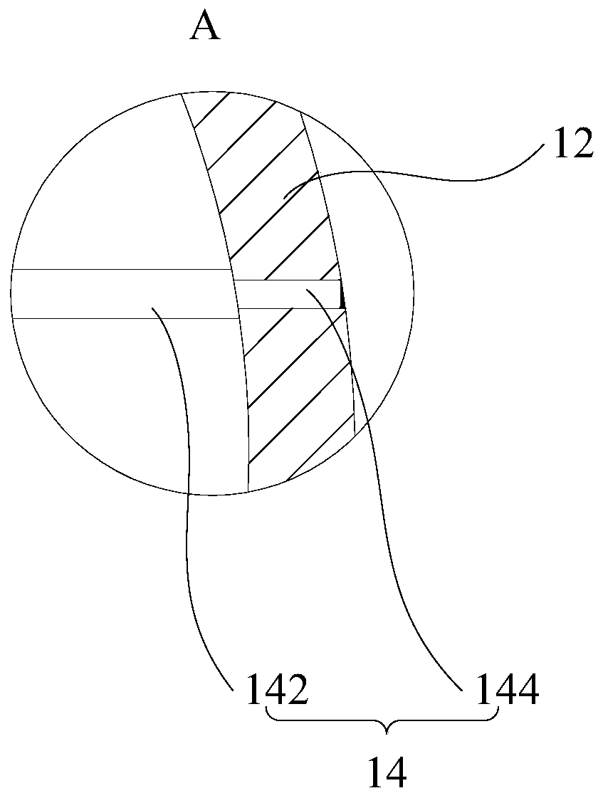
[0032] Refer below Figure 1 to Figure 3 The ultrasonic flow measuring device according to some embodiments of the present invention is described.

[0033] In the embodiment of the present inventio...


PUM


Abstract

The invention provides an ultrasonic flow measuring device. The ultrasonic flow measuring device is connected with a pipeline and comprises a rectifier pipe, blades, a mixing pipe, a porous pipe and diversion holes, wherein the rectifier pipe is a hollow circular pipe with two ends opened, and one end of the rectifier pipe is communicated with the pipeline; at least four plate-shaped blades are evenly embedded in the rectifier pipe, and the blades are connected with the inner wall of the rectifier pipe; the mixing pipe is a hollow circular pipe with two ends opened, and one end of the mixing pipe is communicated with the other end of the rectifier pipe; the porous pipe is a hollow circular pipe with one end opened, and one end of the porous pipe is communicated with the other end of the mixing pipe; and at least two diversion holes are arranged on the porous pipe. By adopting the structure, the structure is simple, and by embedding at least four blades into the rectifier pipe, when thefluid flows into the rectifier pipe and the uneven flow flows through the blades, a flow field is redistributed to eliminate secondary flow, eddy flow and the like.

Description

technical field [0001] The invention relates to the technical field of ultrasonic flow measurement, in particular to an ultrasonic flow measurement device. Background technique [0002] At present, in the related technology, the pipeline is connected with the ultrasonic flowmeter. Due to the existence of flow resistance parts such as elbows and valves, the fluid velocity distribution in the pipeline is distorted and the velocity distribution is asymmetrical. Therefore, only the upstream of the ultrasonic flowmeter can be guaranteed. Only with a long enough straight pipe section can the measurement accuracy be met. In general, in field applications, the requirement for a long enough straight pipe section cannot be met, which limits the application range of the ultrasonic flowmeter. Therefore, in order to meet the measurement accuracy of the ultrasonic flowmeter Under the premise of this, it is very necessary to shorten the length of the straight pipe required by the ultrasoni...

Claims


Application Information

Patent Timeline
Patent Type & Authority Applications(China)
IPC IPC(8): G01F1/66
Inventor 夏前明罗丽娟夏雪梅董海坤刘功源
Owner CHARODEN IND TECH (SHANGHAI) CO LTD
Why Eureka
Try Eureka