Special in-situ rock core holder for high-density electrical parameter monitoring

A technology for holders and cores, applied in the field of in-situ core holders, can solve the problems that are not conducive to the complete preservation of precious cores, difficult to avoid cores, prolonging time, etc.

Inactive Publication Date: 2019-06-04
南京九州勘探技术有限公司
View PDF0 Cites 1 Cited by
  • Summary
  • Abstract
  • Description
  • Claims
  • Application Information

AI Technical Summary

Problems solved by technology

Although this core cutting process makes the test core meet the test conditions, it has the following disadvantages: 1. It destroys the integrity of the test core, so that the test result is limited to characterize a certain local core Due to the characteristics of the section, the test of the already local core sample is more limited to a small local area, which is not conducive to the study of the continuous change of core parameters, and it is more difficult to reflect the characteristics of the rock on a larger scale
2. It increases the procedure and cost of core parameter testing
3. It prolongs the time for timely testing of the core, which is not conducive to obtaining the parameters of the core under in-situ conditions
Although special protection measures will be taken for the core during transportation, it is difficult to avoid the changes in various states of the core during this period, which makes the core already affected by drilling and core mining even more affected. The influence of many factors in the later period
4. It is not conducive to the complete preservation of precious rock cores, and limits the parameter determination of precious rock cores
Related technologies and methods have not been reported at home and abroad

Method used


Image

  • Special in-situ rock core holder for high-density electrical parameter monitoring
  • Special in-situ rock core holder for high-density electrical parameter monitoring
  • Special in-situ rock core holder for high-density electrical parameter monitoring

Examples


Embodiment Construction

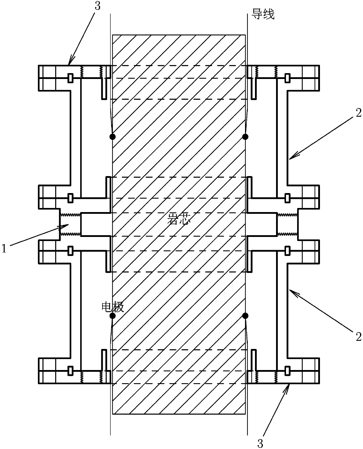
[0016] 1. Fix the long-length rock core to be tested on a certain support. The rock core can be placed horizontally or vertically.

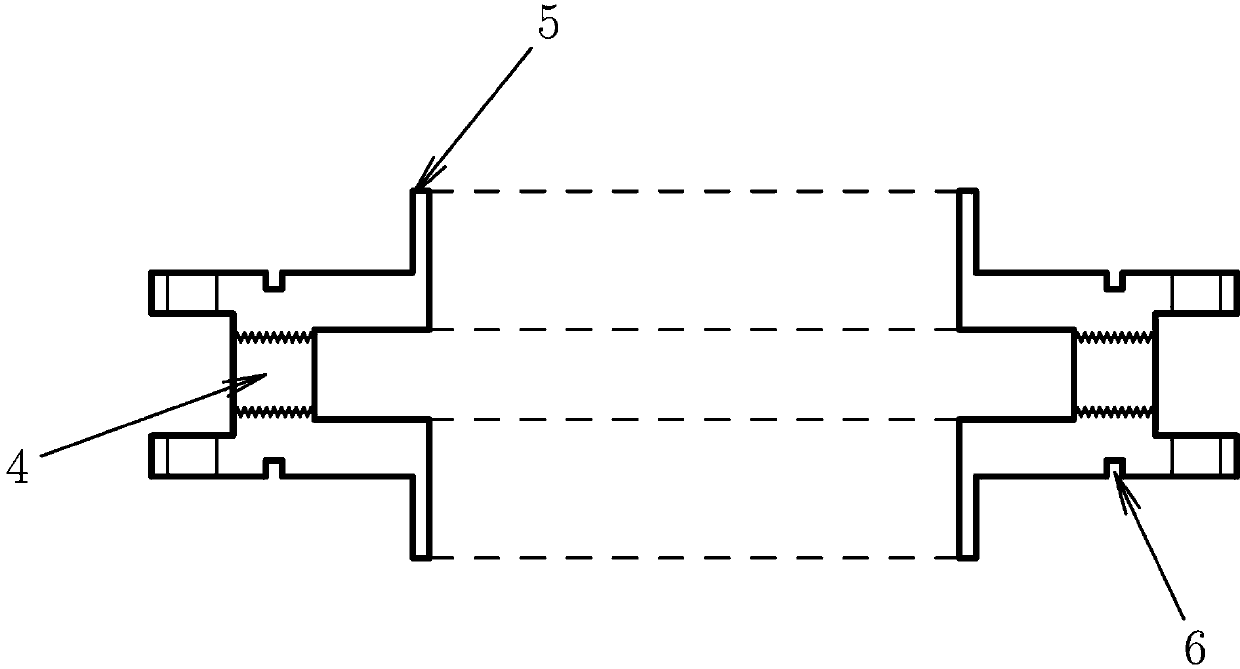
[0017] 2. Install the central part 1 of the holder on a certain position of the rock core to be tested, and mark the positions where the electrodes need to be set on the rock cores on the left and right sides of the central part.

[0018] 3. Set up the electrodes on the rock core, select an insulated wire of appropriate thickness to connect to the electrode, extend the wire along the core axis to both sides and fix it.

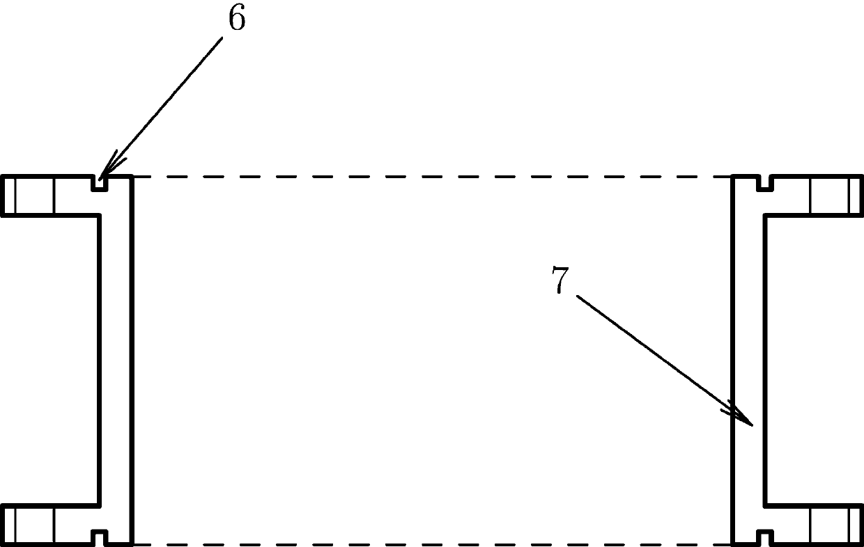
[0019] 4. Set the sleeves on the central part, and install the confining pressure cylinder 2.

[0020] 5. Install the end piece 3, and at the same time put the sleeves on the end piece. The surface of the rock core after the electrodes and wires are installed will be uneven, which can be eliminated by injecting glue, so as to realize the dense connection between the rock core and the sleeve.

[0021]6. Connect and fix parts 1, ...


PUM


Abstract

The invention relates to a special in-situ rock core holder for high-density electrical parameter monitoring, which belongs to the technical field of permeability measurement in the fields such as hydrogeology, geological engineering, petroleum geology, hydrology and water resources, soil science and mineral resources, solves a problem that it is difficult to carry out high-density monitoring on electrical parameter changes in the experimental process on a long rock core without cutting the rock core and provides a core device for measuring the permeability field in different scales and directions or even under heterogeneity at any position on the long rock core. The technical scheme is that a fluid is injected and flows out from the annular side surface of the rock core through a centralcomponent of the holder, both sides are provided with a confining pressure chamber for confining pressure application and high-density electrode arrangement, and then high-density monitoring for the rock core electrical parameters in the process of a hydraulic experiment is realized through extracted wires. The special in-situ rock core holder is completely different from a traditional rock core holder, can carry out high-density electrical parameter monitoring on rock cores with an arbitrary length under different conditions and has extensive applications.

Description

technical field [0001] The in-situ rock core holder of the present invention refers to the rock core holder that can be applied to the longer rock core of the length that is not specially processed and collected on the spot, and is a special device for carrying out rock core determination experiments. The main difference with traditional core holders is that they can be used to measure longer lengths of core without cutting the core in sections, whereas traditional core holders can only measure a limited length of cut (typically 10cm or so) core. Since the main parameter used by the in-situ core holder for determination is still the core permeability, and the permeability is an important basic parameter in the fields of hydrogeology, geological engineering, petroleum geology, hydrology and water resources, soil science, mineral resources, etc. Therefore, the invented in-situ rock core holder belongs to the technical field and is a core component thereof. The traditional core...

Claims


Application Information

Patent Timeline
Patent Type & Authority Applications(China)
IPC IPC(8): G01N15/08
Inventor 不公告发明人
Owner 南京九州勘探技术有限公司
Why Eureka
Try Eureka