A kind of glass fiber crushing equipment and waste silk processing method
A technology of glass fiber and crushing equipment, which is applied in the direction of grain processing, etc., and can solve problems such as easy agglomeration, inability to recycle and crush waste silk, and difficulty in recycling and crushing waste silk
- Summary
- Abstract
- Description
- Claims
- Application Information
AI Technical Summary
Problems solved by technology
Method used
Image
Examples
Embodiment 2
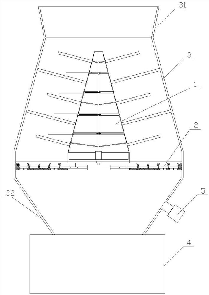
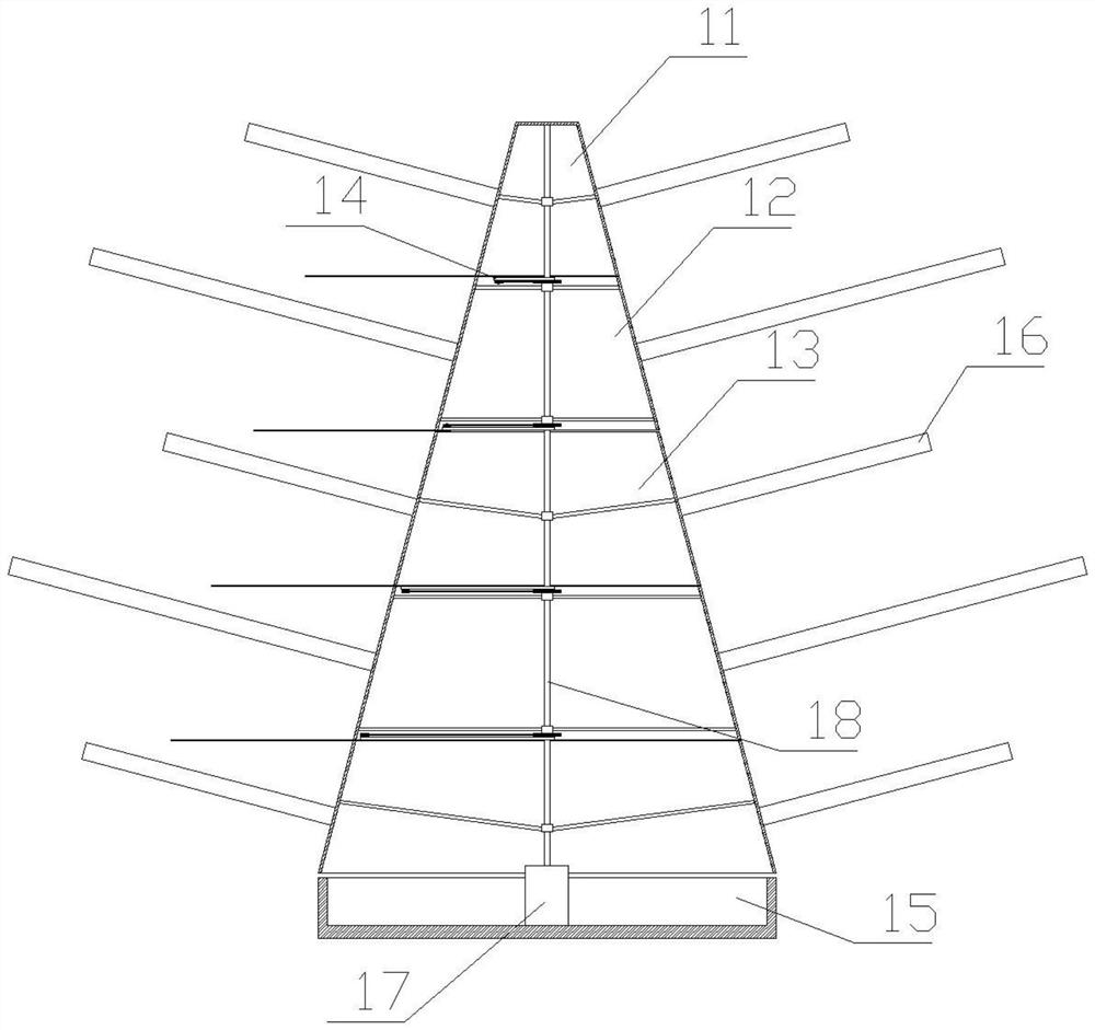
[0038] Such as figure 2 as shown, figure 2It is a schematic structural view of the first cutting device; the first cutting device 1 includes a top cover 11, several fixed parts 12, several rotating parts 13, a cutting assembly 14 and a base 15; the fixed part 12 and the rotating part 13 are arranged alternately between the top cover 11 and the base 15; the first cutting device 1 is set in a circular truncated shape as a whole, and the cross section of the first cutting device 1 gradually becomes larger from top to bottom; The distance between the outer surface of the first cutting device 1 and the inner surface of the cylinder body 3 is consistent; the outer surfaces of the top cover 11, the fixed part 12, and the rotating part 13 are uniformly provided with a number of push rods 16, The dial rod 16 is cylindrical, and the fixed part 12 is fixedly connected with the inner surface of the cylinder body 3 through the dial rod 16; the dial on the top cover 11 and the rotating p...
Embodiment 3
[0044] Such as image 3 as shown, image 3 It is a schematic structural view of the cutting assembly; the cutting assembly 14 includes a cutting knife 141 and a connecting rod 142, and the two ends of the connecting rod 142 are respectively connected to the rotating shaft 18 and the cutting knife 141, and the cutting knife 141 and The connecting position of the connecting rod 142 is provided with a connecting shaft, and the connecting shaft is fixedly connected with the cutting knife 141. The connecting rod 142 is provided with a connecting hole corresponding to the connecting shaft, and the connecting shaft 143 is arranged on the In the connection hole, the cutting knife 141 and the connecting rod 142 can rotate relatively around the connecting shaft 143; the connecting rod 142 is fixedly connected to the rotating shaft 18; the cutting knife 141 has a blade for Cut waste.
[0045] The connecting shaft 143 is also provided with a transmission wheel 144; the rotating shaft 18...
Embodiment 4
[0051] In order to ensure that the cutting knife 141 effectively cuts the waste silk between the fixed part 12 and the rotating part 13, the cutting knife 141 needs to be on the corresponding part of the fixed part 12 and the rotating part 13. Stretch out between the shifting rods 16 to cut the waste silk wound on the two described shifting rods 16; To achieve the best cutting effect. Therefore, the relationship needs to be satisfied:
[0052]
[0053] Wherein, R is the radius of the fixed wheel 145 ; r is the radius of the transmission wheel 144 ; θ is the angle between adjacent shift rods 16 on the same fixed part 12 or the rotating part 13 .
[0054] On the basis of the third embodiment, due to the influence of the length of the connecting rod 142 and the length setting of the cutting knife 141, the working sections where the cutting knife 141 actually stretches out and realizes cutting are all different; Distribute the quantity of described cutting knife 141, all can ...
PUM
 Abstract
Description
Claims
Application Information
 - R&D
- Intellectual Property
- Life Sciences
- Materials
- Tech Scout
- Unparalleled Data Quality
- Higher Quality Content
- 60% Fewer Hallucinations
Browse by: Latest US Patents, China's latest patents, Technical Efficacy Thesaurus, Application Domain, Technology Topic, Popular Technical Reports.
© 2025 PatSnap. All rights reserved.Legal|Privacy policy|Modern Slavery Act Transparency Statement|Sitemap|About US| Contact US: help@patsnap.com


