The invention discloses a high-power lumped element power divider with-45-degree phase delay

A technology of lumped components and phase delay, which is applied in the field of radio frequency/microwave, can solve the problem that Wilkinson power splitter is not suitable for high-power signal transmission, etc., and achieve good thermal power dissipation effect, good port impedance matching performance, and isolation good performance

Inactive Publication Date: 2019-06-11
SHANGHAI INST OF MICROSYSTEM & INFORMATION TECH CHINESE ACAD OF SCI
View PDF5 Cites 8 Cited by
  • Summary
  • Abstract
  • Description
  • Claims
  • Application Information

AI Technical Summary

Problems solved by technology

[0004] In view of the shortcomings of the prior art described above, the object of the present invention is to provide a high-power lumped element power splitter with a -45° phase delay, which is used to solve the problem that the classic Wilkinson power splitter is not suitable for high-power signals. passing problem

Method used


Image

  • The invention discloses a high-power lumped element power divider with-45-degree phase delay
  • The invention discloses a high-power lumped element power divider with-45-degree phase delay
  • The invention discloses a high-power lumped element power divider with-45-degree phase delay

Examples


Embodiment 1

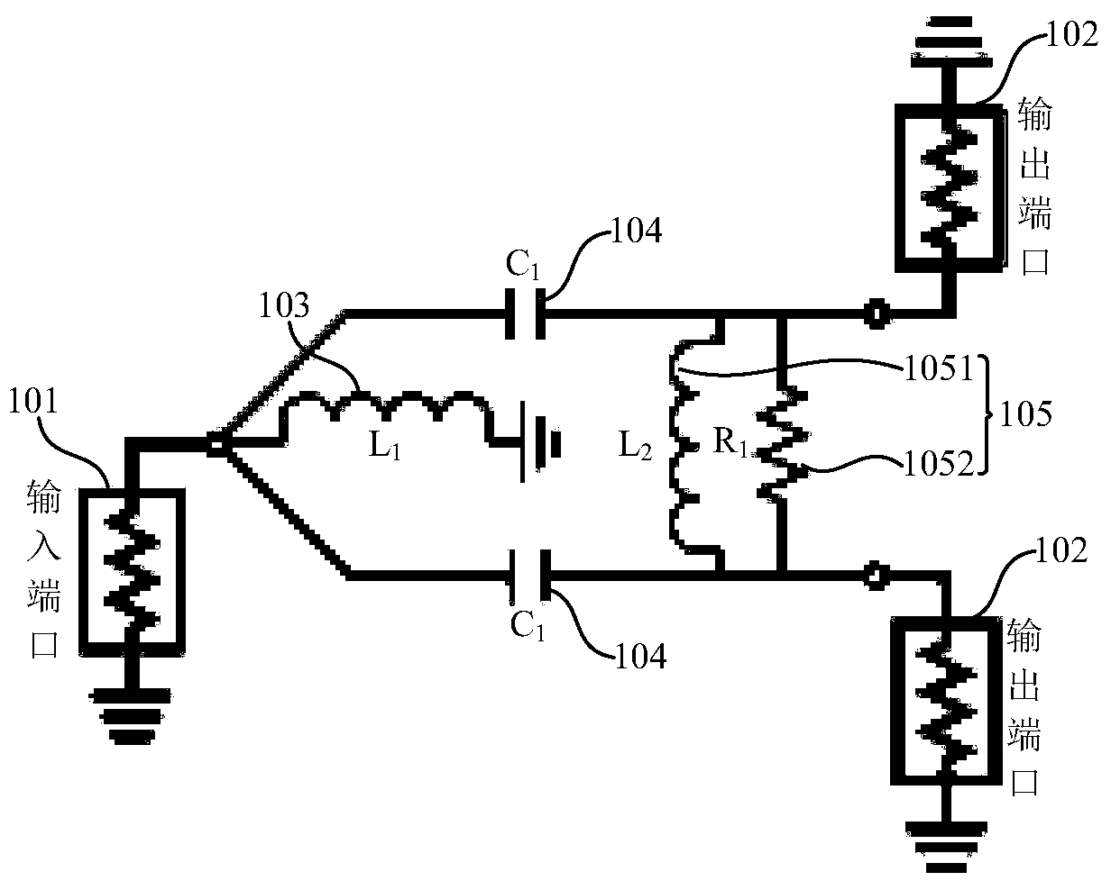
[0036] like figure 1 As shown, this embodiment provides a high-power lumped element power divider with a -45° phase delay, and the power divider includes:

[0037] an input port 101 and two output ports 102;

[0038] A matching inductor 103, one end of which is connected to the input port 101, and the other end of which is grounded;

[0039] Transfer capacitors 104 are respectively connected between the input port 101 and the two output ports 102;

[0040] The isolation unit 105 is connected between the two output ports 102, the isolation unit 105 includes an isolation inductor 1051 and an isolation resistor 1052, wherein the isolation inductor 1051 and the isolation resistor 1052 are connected in parallel to the two between output ports 102.

[0041] It should be noted that the characteristic impedances of the input port 101 and the output port 102 are equal, which is well known to those skilled in the art, so it will not be repeated here.

[0042] As an example, the matc...

Embodiment 2

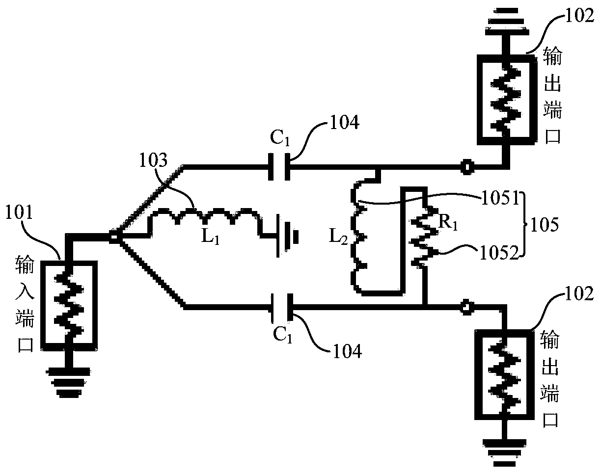
[0051] like figure 2 As shown, this embodiment provides a high-power lumped element power divider with a -45° phase delay, and the power divider includes:

[0052] an input port 101 and two output ports 102;

[0053] A matching inductor 103, one end of which is connected to the input port 101, and the other end of which is grounded;

[0054] Transfer capacitors 104 are respectively connected between the input port 101 and the two output ports 102;

[0055] The isolation unit 105 is connected between the two output ports 102, the isolation unit 105 includes an isolation inductor 1051 and an isolation resistor 1052, wherein the isolation inductor 1051 and the isolation resistor 1052 are connected in series between the two between output ports 102.

[0056] It should be noted that the characteristic impedances of the input port 101 and the output port 102 are equal, which is well known to those skilled in the art, so it will not be repeated here.

[0057] As an example, the ...


PUM


Abstract

The invention provides a high-power lumped element power divider with -45-degree phase delay. The high-power lumped element power divider comprises an input port and two output ports, an matching inductor one end of which is connected to the input port, and the other end is grounded; the transfer capacitors which are respectively connected between the input port and the two output ports; and an isolation unit which is connected between the two output ports, and comprises an isolation inductor and an isolation resistor, wherein the isolation inductor and the isolation resistor are connected inparallel between the two output ports, or the isolation inductor and the isolation resistor are connected in series between the two output ports. According to the invention, the problem that the classic Wilkinson power divider is not suitable for high-power signal transmission is solved.

Description

technical field [0001] The invention relates to the field of radio frequency / microwave technology, in particular to a high-power lumped element power divider with a phase delay of -45°. Background technique [0002] A power divider (referred to as a power divider) is one of the basic components of a microwave circuit. It has a multi-port microwave network that decomposes the input signal power into several isolated equal or unequal power signals, or vice versa. Signals of equal or unequal power are combined into one way, so it is sometimes called a power divider / combiner. Power splitters are widely used in circuits and systems such as power amplification and synthesis, signal testing, quadrature mixing demodulation, and antenna beamforming, and their performance will affect the communication quality of the entire circuit or system. [0003] Among the microstrip power splitters, the Wilkinson (Wilkinson) power splitter has good characteristics due to its own structural chara...

Claims


Application Information

Patent Timeline
Patent Type & Authority Applications(China)
IPC IPC(8): H03H7/52
Inventor 伍文涛王镇
Owner SHANGHAI INST OF MICROSYSTEM & INFORMATION TECH CHINESE ACAD OF SCI
Why Eureka
Try Eureka