
+/-45° Phase-Shifted Dual Bandpass Response Lumped Element Power Divider with Isolation Stopband

A dual-frequency bandpass and lumped element technology, applied in the field of microwave technology research, achieves the effects of suppressing the transmission of harmonic clutter signals, reducing difficulty, and good port impedance matching performance

Active Publication Date: 2021-10-26
SHANGHAI TECH UNIV
View PDF8 Cites 0 Cited by
  • Summary
  • Abstract
  • Description
  • Claims
  • Application Information

AI Technical Summary

Problems solved by technology

[0003] The classic transmission line Wilkinson power divider can only work at the specified operating frequency or its odd harmonics
And the classic lumped element Wilkinson power divider can only work in a single frequency band

Method used


Image

  • +/-45° Phase-Shifted Dual Bandpass Response Lumped Element Power Divider with Isolation Stopband
  • +/-45° Phase-Shifted Dual Bandpass Response Lumped Element Power Divider with Isolation Stopband
  • +/-45° Phase-Shifted Dual Bandpass Response Lumped Element Power Divider with Isolation Stopband

Examples


Embodiment 1

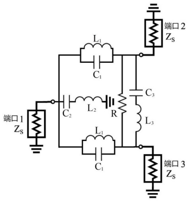
[0046] A basic structural form disclosed in this embodiment is as figure 2 As shown, the lumped element power divider proposed in this embodiment, the lumped element power divider, the phase difference between the signal input port 1 and the output port 2 or output port 3 is ±45° (the low frequency band is 45°, and the high frequency band is 45°. frequency band is -45°). Output port 2 and output port 3 adopt a symmetrical structure, have equal amplitude and phase, and are isolated from each other. The structure of the power divider circuit consists of an inductor L connected in series with the input port 1 to ground 2 and capacitance C 2 , the parallel inductance L from input port 1 to output port 2 and output port 3 respectively 1 and capacitance C 1 , and the isolation resistor R between the two output ports 2 and 3, the series inductor L in parallel with the isolation resistor R 3 , capacitance C 3 composition. The component parameter values ​​of this structure are ...

Embodiment 2

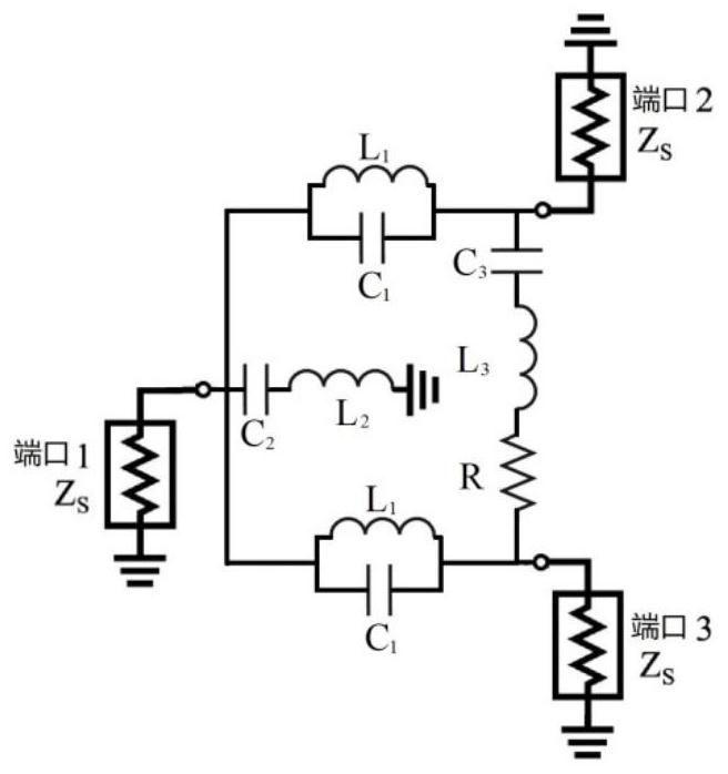
[0056] A basic structural form disclosed in this embodiment is as image 3 As shown, the difference between it and Embodiment 1 is: the isolation resistance R and the inductance L 3 , capacitance C 3 in series. Such as image 3 Component parameter values ​​of the structure shown, L 1 、C 1 , L 2 、C 2 and figure 2 exactly the same, while L 3 、C 3 , the parameter value of R can be calculated by the following formula (8) to formula (10):

[0057] L 3 =L 2 (8)

[0058] C 3 =C 2 (9)

[0059] R=Z s (10)

[0060] Other structures and working principles of this embodiment are the same as those of Embodiment 1.

[0061] The power divider designed according to the formula disclosed in Embodiment 1 or according to the formula disclosed in Embodiment 2 has perfect power distribution, impedance matching and isolation characteristics between output ports at the center operating frequency. And the farther away from the center frequency, the performance of the power spli...


PUM


Abstract

The invention relates to a + / -45° phase-shift dual-frequency band-pass response lumped element power divider with an isolation stop band and a design method thereof. The three ports of the power divider provided by the present invention all have good port impedance matching, and the signal output port 1 and the signal output port 2 have equal amplitude and phase and are isolated from each other. The phase difference between the output port and the input port of the power splitter at the center operating frequency of the low frequency band is 45°, and the phase difference between the output port and the input port of the power splitter at the center operating frequency of the high frequency band is -45°, This is significantly different from the classic dual-frequency Wilkinson power splitter (±90°). Furthermore, between the two operating frequency bands of the novel Wilkinson power divider proposed by the present invention, there is also a wide-frequency stop band, which can effectively suppress the transmission of harmonic clutter signals. In addition, the circuit invention also has the unique advantages of only needing a total of 9 components, wider working bandwidth and the like.

Description

technical field [0001] The present invention relates to a lumped element circuit topology and design method of a miniaturized dual-frequency power distribution / synthesizer, especially the transmission phase shifts of the new power splitter at the center frequencies of its two working frequency bands are respectively 45° and -45° with a wide stopband (transmission zero) in the middle of the two operating bands. The invention belongs to the field of microwave technology research. Background technique [0002] The power divider / combiner is one of the basic components of a microwave circuit. It has the function of decomposing the input signal power into several isolated signals with equal or unequal power, or conversely combining several signals into one. Therefore, power splitters are widely used in circuits and systems such as power amplification and synthesis, signal testing, and quadrature mixing and demodulation. There are many forms of power splitters, such as couplers (...

Claims


Application Information

Patent Timeline
Patent Type & Authority Patents(China)
IPC IPC(8): H01P5/16
CPCH01P5/16
Inventor 杨瑾屏
Owner SHANGHAI TECH UNIV
Learn More