Colorful filter with touch function and liquid crystal display device

A liquid crystal display device, color filter technology, applied in optics, optical elements, nonlinear optics, etc., can solve the problems of light leakage, light transmittance, easy generation of bubbles, low reliability, etc.

Inactive Publication Date: 2009-10-07
WINTEK CORP
View PDF0 Cites 16 Cited by
  • Summary
  • Abstract
  • Description
  • Claims
  • Application Information

AI Technical Summary

Problems solved by technology

However, such an assembly method will result in a large amount of gaps between the touch panel 102 and the liquid crystal panel 104, which may easily cause light leakage and reduce the light transmittance.
Therefore, if figure 2 The design of another conventional liquid crystal display device 200 shown is to use an optical adhesive 206 to bond the touch panel 202 and the liquid crystal panel 204 in a

Method used


Image

  • Colorful filter with touch function and liquid crystal display device
  • Colorful filter with touch function and liquid crystal display device
  • Colorful filter with touch function and liquid crystal display device

Examples


Example Embodiment

[0045] The foregoing and other technical contents, features, and effects of the present invention will be clearly presented in the following detailed description of the embodiments with reference to the drawings. The directional terms mentioned in the following embodiments, for example: up, down, left, right, front or back, etc., are only directions for referring to the attached drawings. Therefore, the directional terms used are used to illustrate but not to limit the present invention.

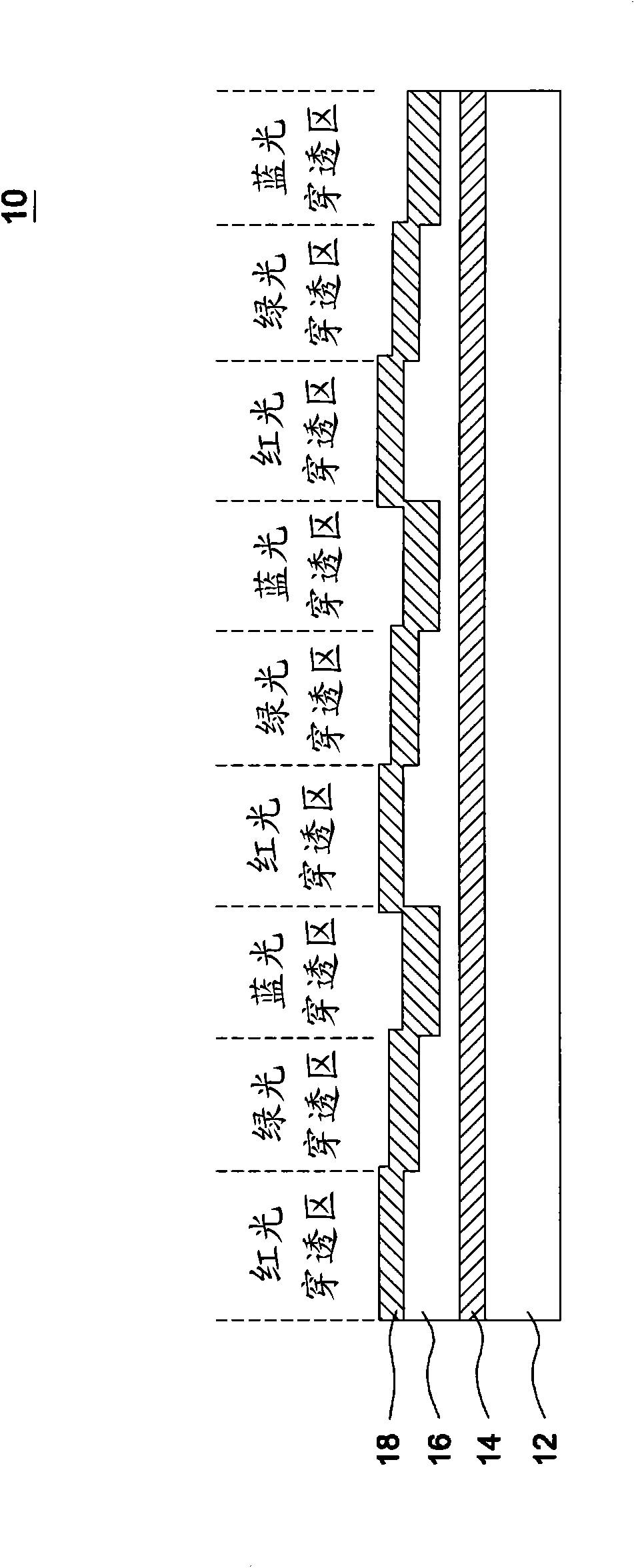
[0046] image 3 It is a schematic diagram showing the color filter 10 with touch function according to an embodiment of the present invention. Such as image 3 As shown, a first semi-permeable conductive layer 14, a gap layer 16 and a second semi-permeable conductive layer 18 are sequentially deposited on the transparent substrate 12. The semi-permeable conductive layers 14, 18 and the gap layer 16 can be formed on the transparent substrate 12 by vacuum coating methods such as evaporation or sp...


PUM


Abstract

The invention relates to a colorful filter with touch function, comprising: a transparent substrate, a conductive layer, a filter layer and a protective layer, wherein the conductive layer is formed on the transparent substrate to sense a touch signal and provided with boundary electrodes on the periphery thereof, the filter layer is formed on the conductive layer, and the protective layer is formed on the filter layer. The filter layer comprises a plurality of red light penetrating zones, green light penetrating zones and blue light penetrating zones, and a pixel unit of a liquid crystal display device at least covers one red light penetrating zone, a green light penetrating zone and a blue light penetrating zone respectively.

Description

technical field [0001] The invention relates to a color filter with touch function and a liquid crystal display device including the color filter. Background technique [0002] figure 1 It is a schematic diagram of a conventional liquid crystal display device 100 with touch function. Such as figure 1 As shown, the liquid crystal display device 100 includes a touch panel 102 and a liquid crystal panel 104 , and the touch panel 102 is pasted on the liquid crystal panel 104 by a double-sided adhesive 106 to combine them. However, this assembling method will result in a large amount of gaps between the touch panel 102 and the liquid crystal panel 104 , and such gaps will easily cause light leakage and reduce the light transmittance. Therefore, if figure 2 The design of another conventional liquid crystal display device 200 shown is to use an optical adhesive 206 to bond the touch panel 202 and the liquid crystal panel 204 in a full-surface adhesive manner to solve the probl...

Claims


Application Information

Patent Timeline
IPC IPC(8): G02F1/1335G02B5/23G06F3/041
Inventor 郭建忠
Owner WINTEK CORP
Why Eureka
Try Eureka