Over-temperature protection circuit

An over-temperature protection circuit and circuit technology, applied in emergency protection circuit devices, circuit devices, emergency protection devices with automatic disconnection, etc., can solve problems such as temperature hysteresis, complex circuit structure, and large layout area, and achieve convenient The effect of debugging, simple circuit structure, and small number of components

Active Publication Date: 2015-10-07
UNIV OF ELECTRONIC SCI & TECH OF CHINA
View PDF3 Cites 16 Cited by
  • Summary
  • Abstract
  • Description
  • Claims
  • Application Information

AI Technical Summary

Problems solved by technology

[0006] In order to solve the disadvantages of the traditional over-temperature protection scheme that the circuit structure is relatively complicated, high-precision comparators are needed, and the layout area is

Method used


Image

  • Over-temperature protection circuit
  • Over-temperature protection circuit
  • Over-temperature protection circuit

Examples


Embodiment Construction

[0022] Embodiments of the present invention are described below through specific examples, and those skilled in the art can easily understand other advantages and effects of the present invention from the content disclosed in this specification. The present invention can also be implemented or applied through other different specific implementation modes, and various modifications or changes can be made to the details in this specification based on different viewpoints and applications without departing from the spirit of the present invention.

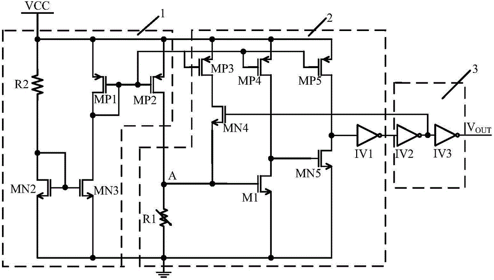
[0023] Such as figure 2 As shown, an over-temperature protection circuit includes: a constant current generating circuit 1, an output control circuit 2, and an output shaping circuit 3. The constant current generating circuit 1 is used to provide a stable current bias for the over-temperature protection circuit; The output control circuit 2 is used to convert the temperature signal into an electrical signal, and control the output of...


PUM


Abstract

The invention discloses an over-temperature protection circuit. The over-temperature protection circuit comprises a constant current generation circuit, an output control circuit and an output shaping circuit. The constant current generation circuit is used for providing a stable current bias for the over-temperature protection circuit. The output control circuit is used for converting a temperature signal into an electric signal and controlling output of the over-temperature protection circuit. The output shaping circuit is used for shaping output of an output signal of the output control circuit. A first resistor and an M1 tube are used for real-time detection of a chip temperature and making a response. The over-temperature protection circuit is simple in structure, and does not need any high-precision voltage comparator. The component number is low, temperature control precision is high, a turn-off signal can be generated at a heat turn-off temperature threshold point accurately, debugging is convenient, the over-temperature protection circuit has a temperature hysteresis function, heat oscillation of the chip near the temperature threshold point is prevented, and the over-temperature protection circuit is suitable for usage in chips of power supply management or LED driving and the like.

Description

technical field [0001] The invention relates to an over-temperature protection circuit used in electronic circuits, which is suitable for the field of analog integrated circuits. Background technique [0002] With the continuous development of integrated circuit technology, the integration of integrated circuits is increasing, the number of components integrated on a single chip is increasing, and the power consumption of the chip is increasing. Some integrated circuits such as switching power supplies, drive circuits, etc. We often face the problem that the temperature of the chip rises too fast near the power tube. Excessive temperature will seriously affect the performance and reliability of the chip, and even cause permanent damage to the chip. [0003] In order to avoid damage to the chip caused by excessive temperature, it is necessary to integrate an over-temperature protection circuit near the power tube of the chip. When the local temperature of the chip reaches a c...

Claims


Application Information

Patent Timeline
IPC IPC(8): H02H5/04
Inventor 乔明陈钢李阳张晓菲李妍月张波
Owner UNIV OF ELECTRONIC SCI & TECH OF CHINA
Why Eureka
Try Eureka