
Electrical junction box

a technology of electrical junction box and water outlet, which is applied in the direction of lighting conductor installation, electrical apparatus casing/cabinet/drawer details, casing/cabinet/drawer details, etc., can solve the problems of high pressure cleaning water intruding incurring a cost increase, etc., to avoid the introduction of water into the interior of the electrical junction box, avoid the increase of the number of components, and avoid the effect of assembling

Inactive Publication Date: 2006-03-28
YAZAKI CORP
View PDF10 Cites 15 Cited by
  • Summary
  • Abstract
  • Description
  • Claims
  • Application Information

AI Technical Summary

Benefits of technology

[0009]It is therefore an object of the present invention to provide a favorable electrical junction box in which an intrusion of water can be prevented without incurring a rise of cost.
[0014]a water prevention wall, provided on an upper face of a base part of a the fixing leg so as to prevent an intrusion of water into the butting area.
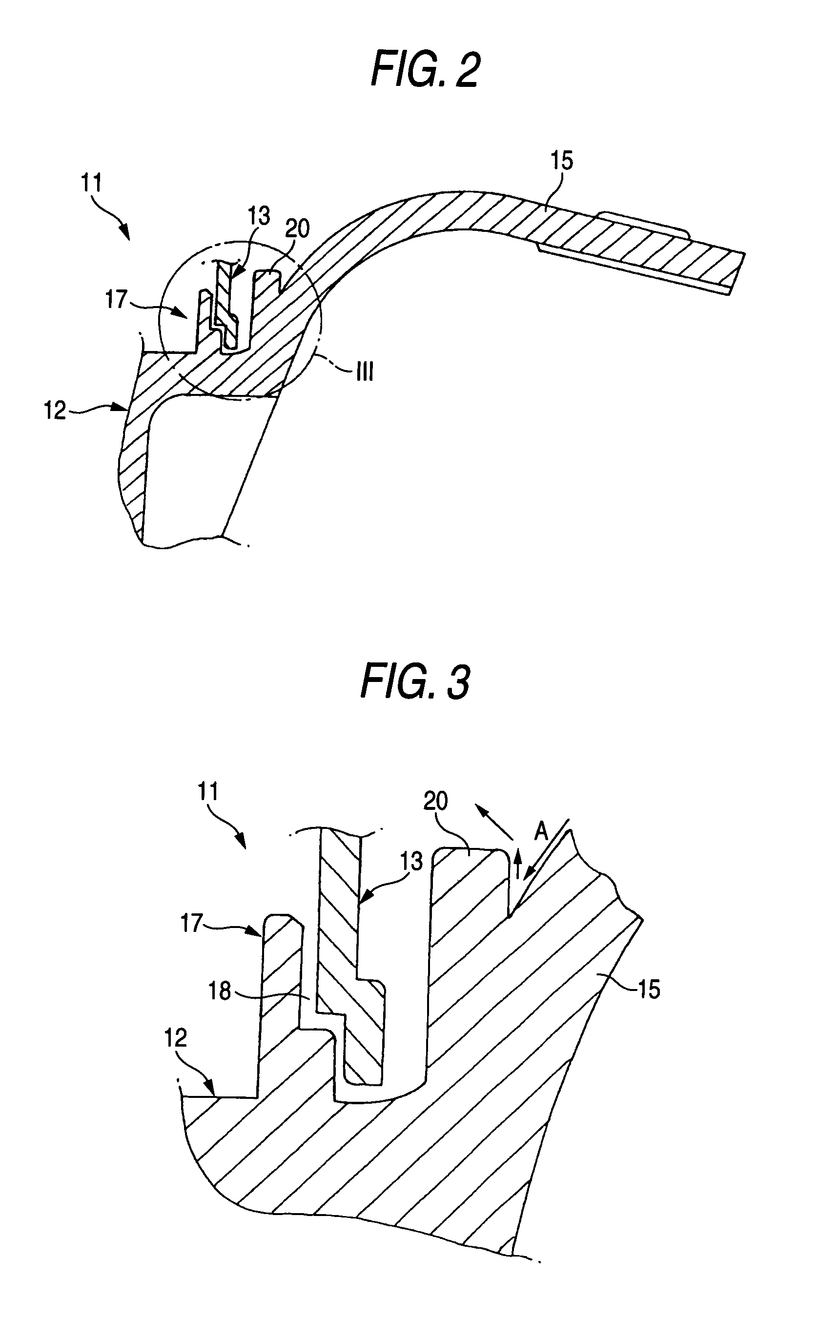
[0021]Then, the water which has collided against the water prevention wall will not flow into the gap at the butting area between the body of the electric junction box and the lid with a strong force, because running force of the water is decreased or a direction of the flow is dispersed, and hence, the intrusion of the water into the interior of the electrical junction box will be prevented.
[0022]Further, the water prevention wall is provided in a projecting manner by integral molding with the body of the electrical junction box, there is no need of employing a separate part such as a packing, and a rise of the cost due to an increase of components in number and assembling works can be avoided.

Problems solved by technology

Accordingly, there has been such an anxiety that the high pressure cleaning water may intrude with water pressure to an interior of the electrical junction box 1.
On the other hand, in case where a packing 9 is provided in the butting area 7 between the body 2 of the electrical junction box and the lid member 3 in order to prevent an intrusion of the water to the interior of the electrical junction box 1, it has been a problem that a separate member, namely, the packing 9 is required, which may incur a rise of cost.

Method used


Image

  • Electrical junction box
  • Electrical junction box
  • Electrical junction box

Examples


Embodiment Construction

[0031]An embodiment of the invention will be described in detail referring to the attached drawings.

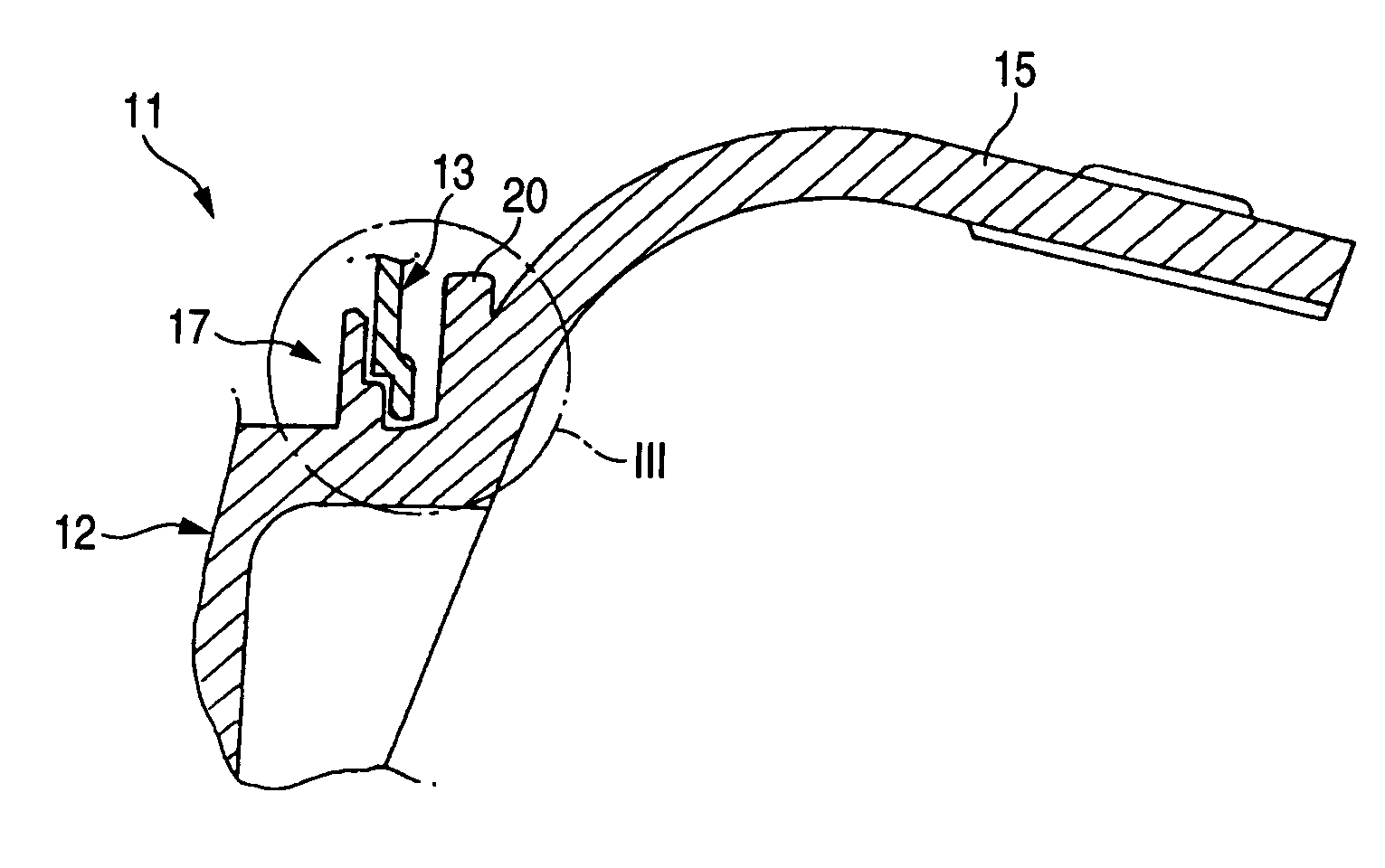
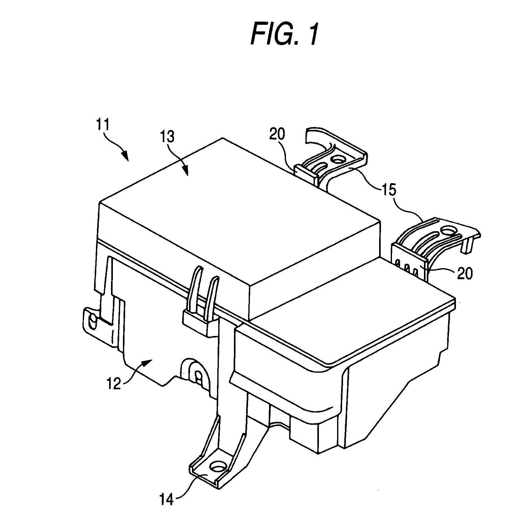
[0032]FIG. 1 is a perspective view showing a general structure of an electrical junction box according to an embodiment of the invention, FIG. 2 is a sectional view of an essential part of the electrical junction box as shown in FIG. 1, and FIG. 3 is an enlarged sectional view of a part denoted by III in FIG. 2.

[0033]The electrical junction box 11 in the present embodiment is a fuse box for containing electrical function components such as fuses, relays in a containing space which is defined by a body 12 of the electrical junction box made of synthetic resin and a lid member 13 covering an upper open part of the body 12 of the electrical junction box and made of synthetic resin.

[0034]It is to be noted that inside the containing space of the body 12 of the electrical junction box, there is installed and fixed a relay and fuse storing part (not shown) which includes a plurality of fuse ...


PUM


Abstract

An electrical junction box includes a main body, having a contain portion for containing electric function components therein, a lid member, covering an open part of the main body, a fixing leg, provided so as to extend from a side wall of the main box being near a butting area in which the lid member is engaged with the main body, and the fixing leg mounted to an exterior structure and a water prevention wall, provided on an upper face of a base part of a the fixing leg so as to prevent an intrusion of water into the butting area.

Description

BACKGROUND OF THE INVENTION[0001]The present invention relates to an electrical junction box, and more particularly to the electrical junction box in which an intrusion of water through a butting area between a body of the electrical junction box and a lid member can be prevented, especially, when the electrical junction box is mounted on a vehicle.[0002]FIG. 4 is a perspective view generally showing an example of a related electrical junction box.[0003]This electrical junction box 1 is intended to contain electrical function components such as fuses, relays and so on in a containing space which is defined by a body 2 of the electrical junction box and a lid member 3 covering an upper open part of the body 2 of the electrical junction box.[0004]The electrical junction box 1 is fixed with bolts or the like to a vehicle panel (an exterior structure) or the like in an engine room by a plurality of fixing legs 4, 5 which are provided so as to extend from the body 2 of the electrical jun...

Claims


Application Information

Patent Timeline
Patent Type & Authority Patents(United States)
IPC IPC(8): H01J5/02H02G13/00H02G3/10H02G3/14H05K5/02H02G3/08H05K7/02
CPCH05K7/026H02G3/088
Inventor OKADA, EIJI
Owner YAZAKI CORP
Learn More