
Outboard motor

a technology for outboard motors and motors, which is applied in the field of outboard motors, can solve the problems of deteriorating engine output power, low possibility of water entering the surface boat, and not likely to block the filter provided on the surface boat, and achieve the effect of reducing or eliminating water

Active Publication Date: 2009-04-14
YAMAHA MOTOR CO LTD
View PDF4 Cites 6 Cited by
  • Summary
  • Abstract
  • Description
  • Claims
  • Application Information

AI Technical Summary

Benefits of technology

The system effectively prevents water intrusion and maintains engine output power by detecting and addressing filter clogs, reducing air intake resistance and ensuring efficient air intake, thus enhancing the reliability and performance of outboard motors.

Problems solved by technology

However, due to their structure, is not likely for the filter provided on the surface boats to get clogged.
Thus, surface boats have only a low possibility of having water enter directly into the intake passage of the engine.
If a water-repellent filter is provided in the air duct of the outboard motor, it can prevent the water intrusion into the engine accommodating chamber, but the filter may be clogged frequently, possibly resulting in deterioration of engine output power in certain cases.
In addition, if the water-repellent filter is clogged by saline matter in seawater, dust, or other foreign matters, the negative pressure within the cowling will increase in magnitude due to the additional air intake resistance, thus possibly resulting in water intrusion through tiny gaps in the cowling that remain sealed during normal operation.
Other problems such as insufficient engine output power may result due to the additional air intake resistance, which will impair the air intake efficiency.
Thus, it is not practicable to apply the water-repellent filter used on the above-mentioned surface boat to the outboard motors.

Method used


Image

  • Outboard motor
  • Outboard motor
  • Outboard motor

Examples


Embodiment Construction

[0028]FIGS. 1 through 6 illustrate an outboard motor according to an embodiment of the present invention.

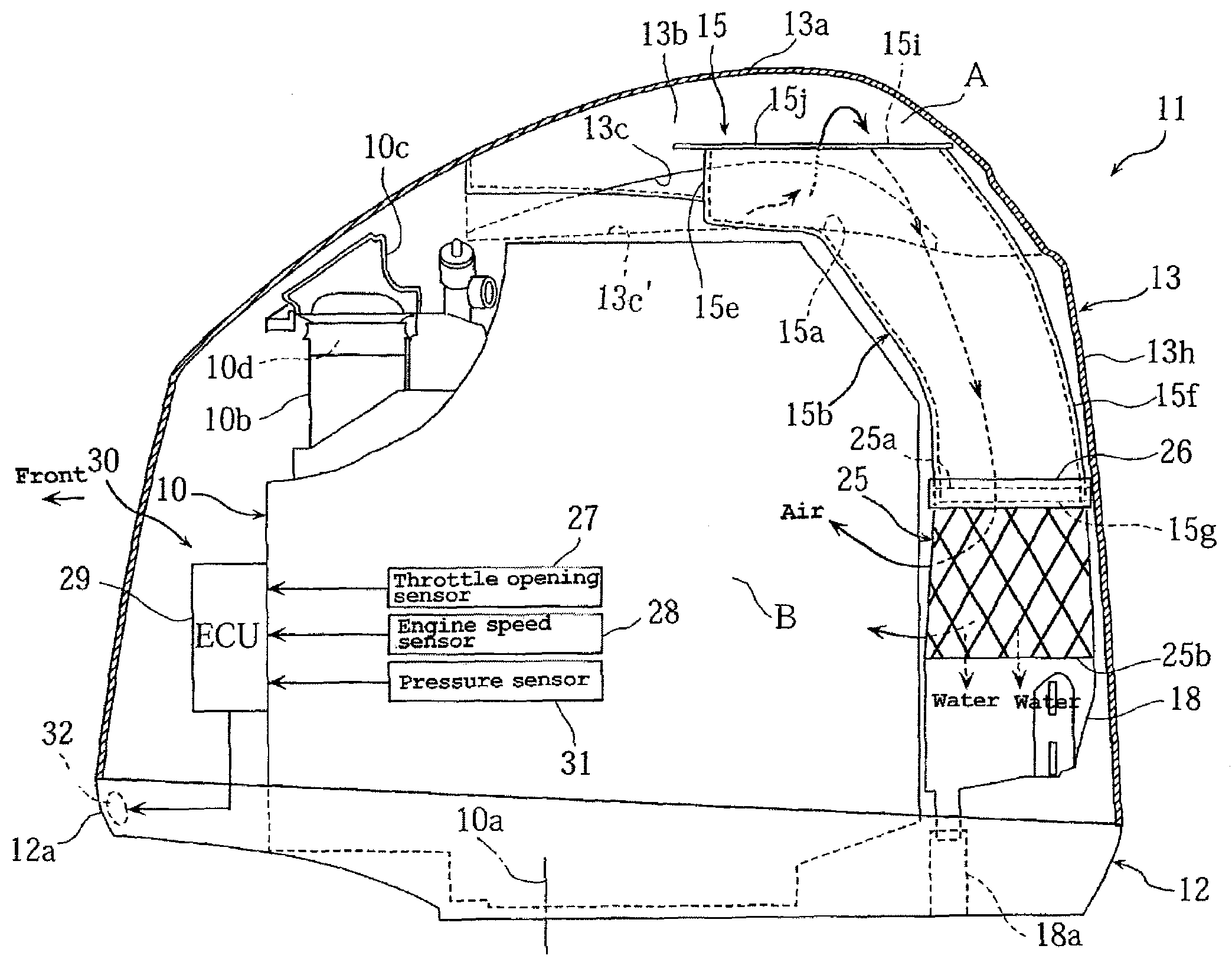
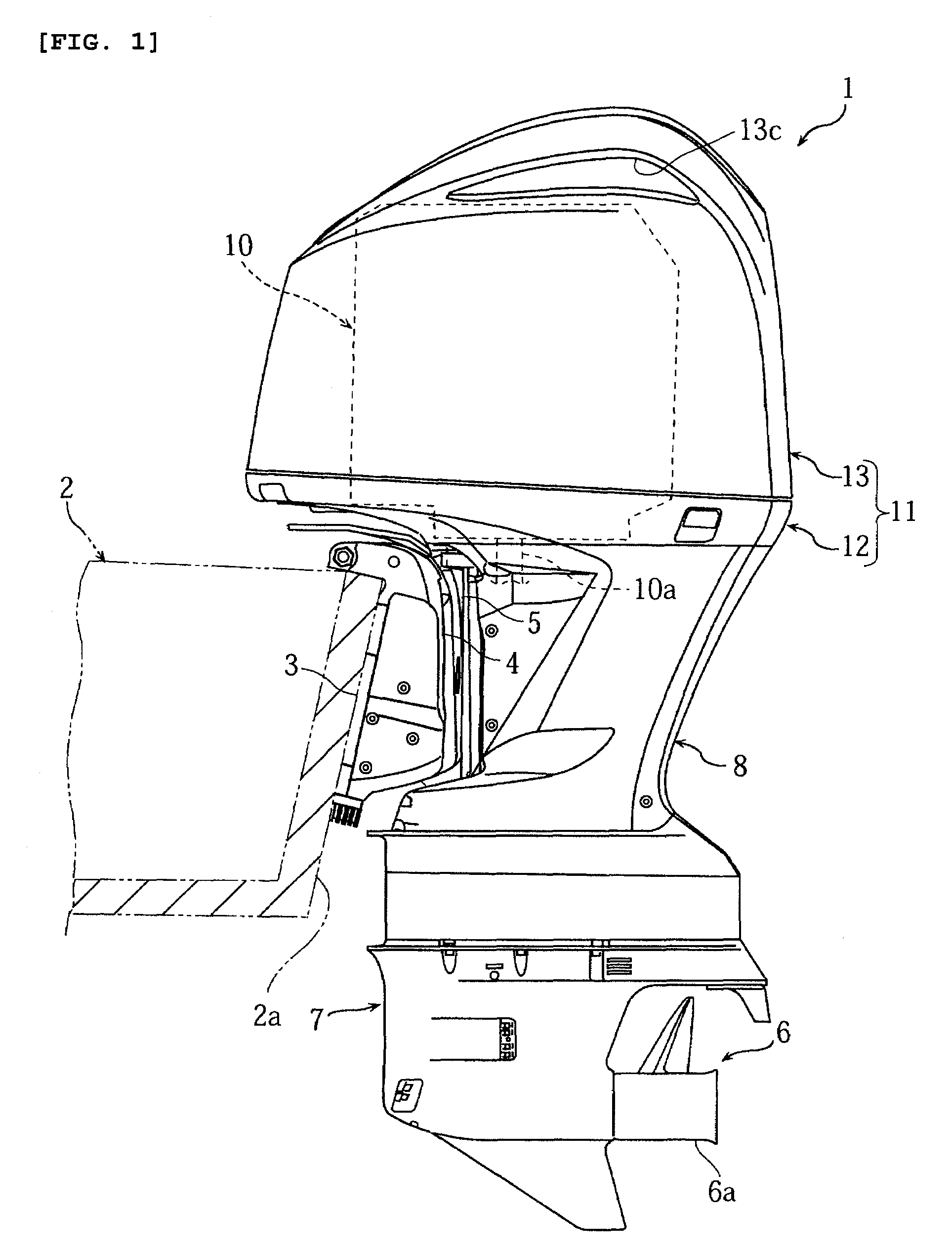
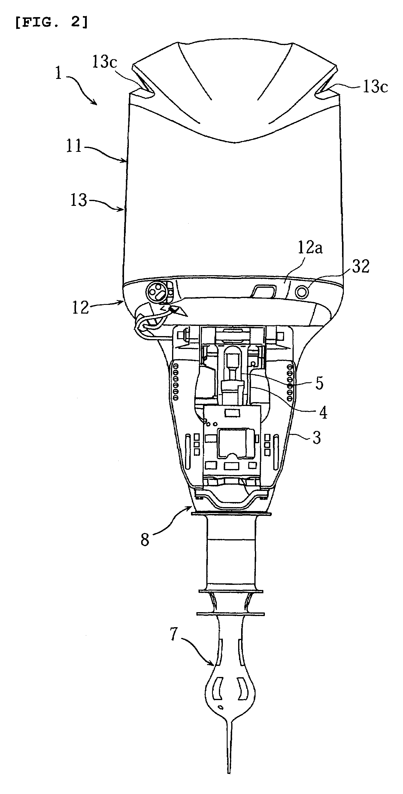
[0029]FIG. 1 is a side view of the outboard. FIG. 2 is a front view of the outboard motor. FIG. 3 is a sectional side view of a cowling accommodating an engine. FIG. 4 is a perspective view of the cowling. FIG. 5 is a cross sectional view of an air duct (cross sectional view along the line V-V in FIG. 4). FIG. 6 is a cross sectional view of an air duct (cross sectional view along the line VI-VI in FIG. 5). Note that the terms “right,”“left,”“front” and “rear” mean right, left, front and rear sides which are defined as viewed from the bow of a boat.

[0030]In the figures, the numeral 1 refers to the outboard motor mounted at a stern 2a of a boat body 2. The outboard motor 1 preferably is supported by a clamp bracket 3 fastened to the stern 2a, in a vertically swingable manner by means of a swivel arm 4, and in a steerable manner to both sides by means of a pivot shaft 5.

[0031]The il...


PUM


Abstract

An outboard motor has an engine, a cowling for accommodating the engine, and an air duct for introducing ambient air into the cowling 11. An air filter is provided in the air duct. One or more sensors detect when the air filter is clogged. When air filter clogging is detected, a warning signal is triggered.

Description

CROSS-REFERENCE TO RELATED APPLICATIONS[0001]The present application is based on and claims priority under 35 U.S.C. §119 to Japanese Patent Application Serial No. 2006-167946, filed on Jun. 16, 2006, the entire contents of which are expressly incorporated by reference herein.BACKGROUND[0002]1. Field of the Invention[0003]This invention relates to an outboard motor provided with a cowling for accommodating an engine and an air duct for introducing ambient air into the cowling.[0004]2. Description of the Related Art[0005]Outboard motors typically are mounted at the stern of the boat. This positioning subjects the outboard motor to water splashes and the like during operation of the boat. Simultaneously, a cowling of an outboard motor must allow air to flow into the cowling to provide intake air for the engine. Accordingly most outboard motor cowlings have a water separation structure that separates water from the air inducted into the cowling and supplies the air to the engine.[0006]...

Claims


Application Information

Patent Timeline
Patent Type & Authority Patents(United States)
IPC IPC(8): B63H21/36
CPCF02M35/09
Inventor TAKAHASHI, MASANORIHIRAOKA, NORIYOSHINAGASHIMA, MITSURUITO, YU
Owner YAMAHA MOTOR CO LTD
Learn More