Laser surveying instrument

a technology of laser surveying and laser scanning, which is applied in the direction of surveying instruments, instruments, height/levelling measurement, etc., can solve the problems that the perfect waterproof effect cannot be obtained, and the intrusion of water and dust from outside cannot be prevented, so as to achieve effective water prevention and dust prevention effect, prevent water intrusion, and prevent water intrusion

Active Publication Date: 2009-04-21
KK TOPCON
View PDF8 Cites 6 Cited by
  • Summary
  • Abstract
  • Description
  • Claims
  • Application Information

AI Technical Summary

Benefits of technology

[0017]It is an object of the present invention to provide a laser surveying instrument, by which it is possible to improve the waterproof function of the water preventing means disposed between the rotating portion and the fixed portion, and to have better water preventing function.
[0019]According to the present invention, there are provided a rotating unit for projecting a laser beam by rotary irradiation, a main unit for rotatably supporting the rotating unit, and a sealing means for sealing between the rotating unit and the main unit, and the sealing means comprises annular ridges formed on the main unit concentrically to the rotation center of the rotating unit, and annular grooves formed on the rotating unit so that the annular ridges are engaged in the annular grooves and gaps are formed between the annular ridges and the annular grooves, the annular ridges and the annular grooves being arranged concentrically to each other and disposed at least in double arrangement, and the sealing means further comprises a route bent and crooked in a radial direction by the gaps, and a cavity disposed at least at one point along the route and having larger volume than the volume of the gap. As a result, the intrusion of water and dust can be prevented by using a route with windings and bendings. Also, capillary phenomenon can be excluded by the cavity, and the intrusion of water can be prevented.
[0020]Also, according to the present invention, the annular ridges at least include a first annular ridge formed at an outer position and a second annular ridge formed at an inner position, and the second annular ridge is higher than the first annular ridge, and the cavity is formed at a point closer to the first annular ridge between the second annular ridge and the annular groove where the second annular ridge is engaged. The water intruding by running over the first annular ridge is trapped and stays in the cavity, and the intrusion of water to the inner space is suppressed. When the surface level of the water staying in the cavity is higher than the first annular ridge, the intrusion of the water into the inner space can be prevented by the pressure of the water trapped and staying in the cavity.
[0021]Further, according to the present invention, an eave protruding in an outward direction is provided on an upper end of the second annular ridge, the cavity is disposed under the eave, and a lower surface of the eave is at a position higher than the first annular ridge. When the surface level of the water staying in the cavity is higher than the first annular ridge, the intrusion of the water into the inner space can be prevented by a pressure of the staying water. Also, the intrusion of the water staying in the cavity into the inner space can be prevented when the main unit is tilted or placed at lateral position.
[0022]Also, according to the present invention, at least inner peripheral surface of at least one of the annular ridges is tilted in an outward direction toward the upper end. When the main unit is tilted or the main unit is pulled down, the intruding water in the route can be effectively discharged to outside by gravitational force.
[0023]Further, according to the present invention, the rotating unit is mounted so as to sandwich a flat plate which is a part of the main unit, the first annular ridge and the second annular ridge are disposed on an upper surface of the flat plate, a third annular ridge is formed on a lower surface of the flat plate, and an annular groove where the third annular ridge is inserted on non-contact basis is formed on a portion of the rotating unit to face toward the lower surface. Water and dust intruding to the central portion are further sealed by the third annular ridge and the annular groove on the rear side, and effective water-preventive and dust preventive effects can be attained.

Problems solved by technology

In such case, gradual intrusion of water from outside cannot be prevented.
Therefore, by the conventional type water preventive means, perfect waterproof effect cannot be necessarily obtained when the surveying instrument is used under severe rainy condition or under rainy weather for long time.

Method used


Image

  • Laser surveying instrument
  • Laser surveying instrument
  • Laser surveying instrument

Examples


second embodiment

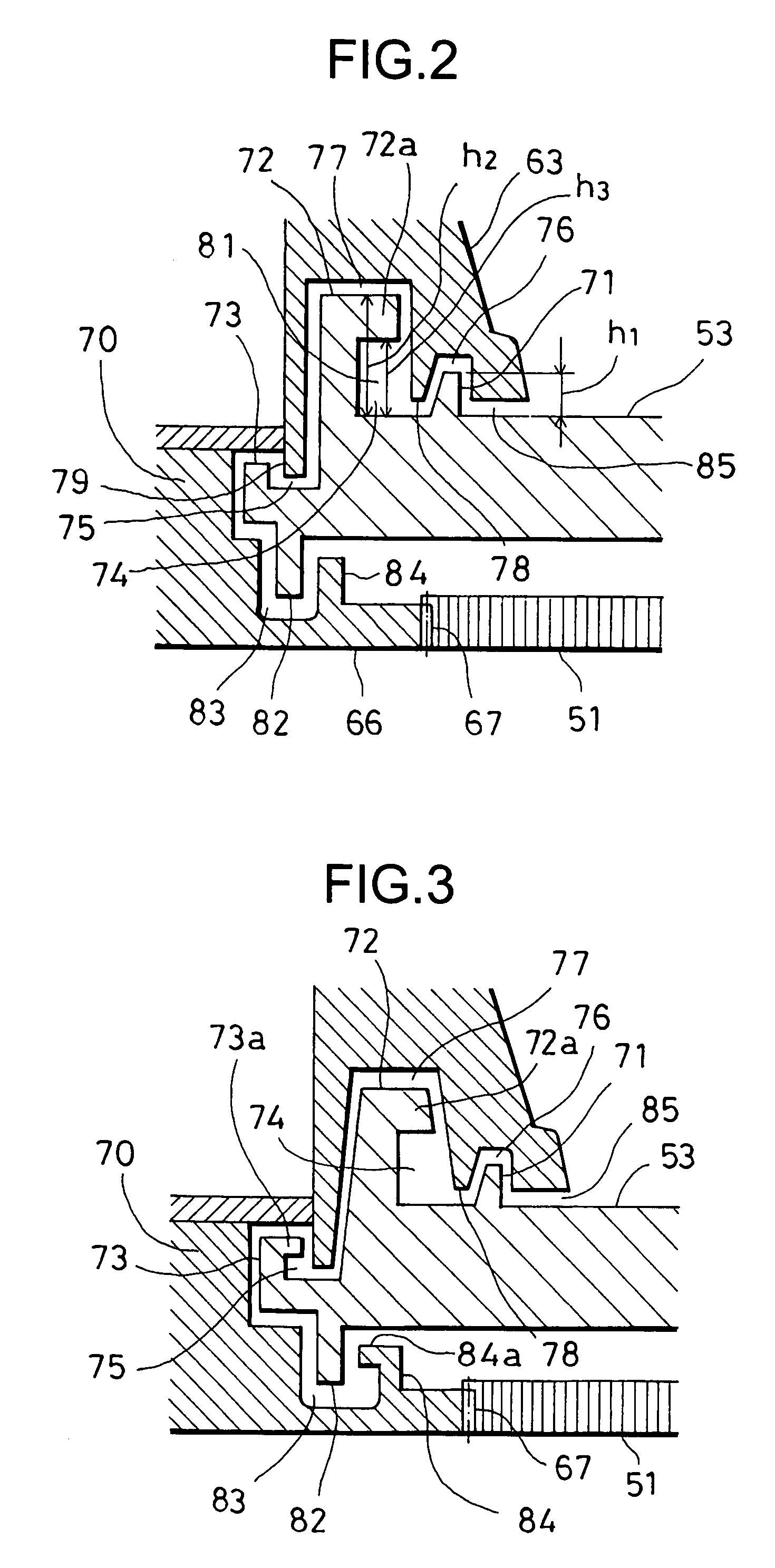
[0082]FIG. 3 shows the invention. When the laser surveying instrument 24 is placed at lateral position, the intruding water can be effectively discharged toward outside in this embodiment.

[0083]The inner peripheral surface of the second annular ridge 72 is tilted so that the second annular ridge 72 is spread in an upward direction, and the outer peripheral surface of the eave 72a is tilted so that it is spread in a downward direction. The groove wall of the fourth annular groove 77 (inner peripheral surface of the fourth annular ridge 78) is tilted so that the groove wall runs in parallel to the inner peripheral surface of the second annular ridge 72 and the outer peripheral surface of the eave 72a. An eave 73a protruding outward is formed on the upper end of the third annular ridge 73, and an eave 84a protruding in an inward direction is formed on the upper end of the seventh annular ridge 84.

[0084]By tilting the inner peripheral surface of the second annular ridge 72 and the outer...

third embodiment

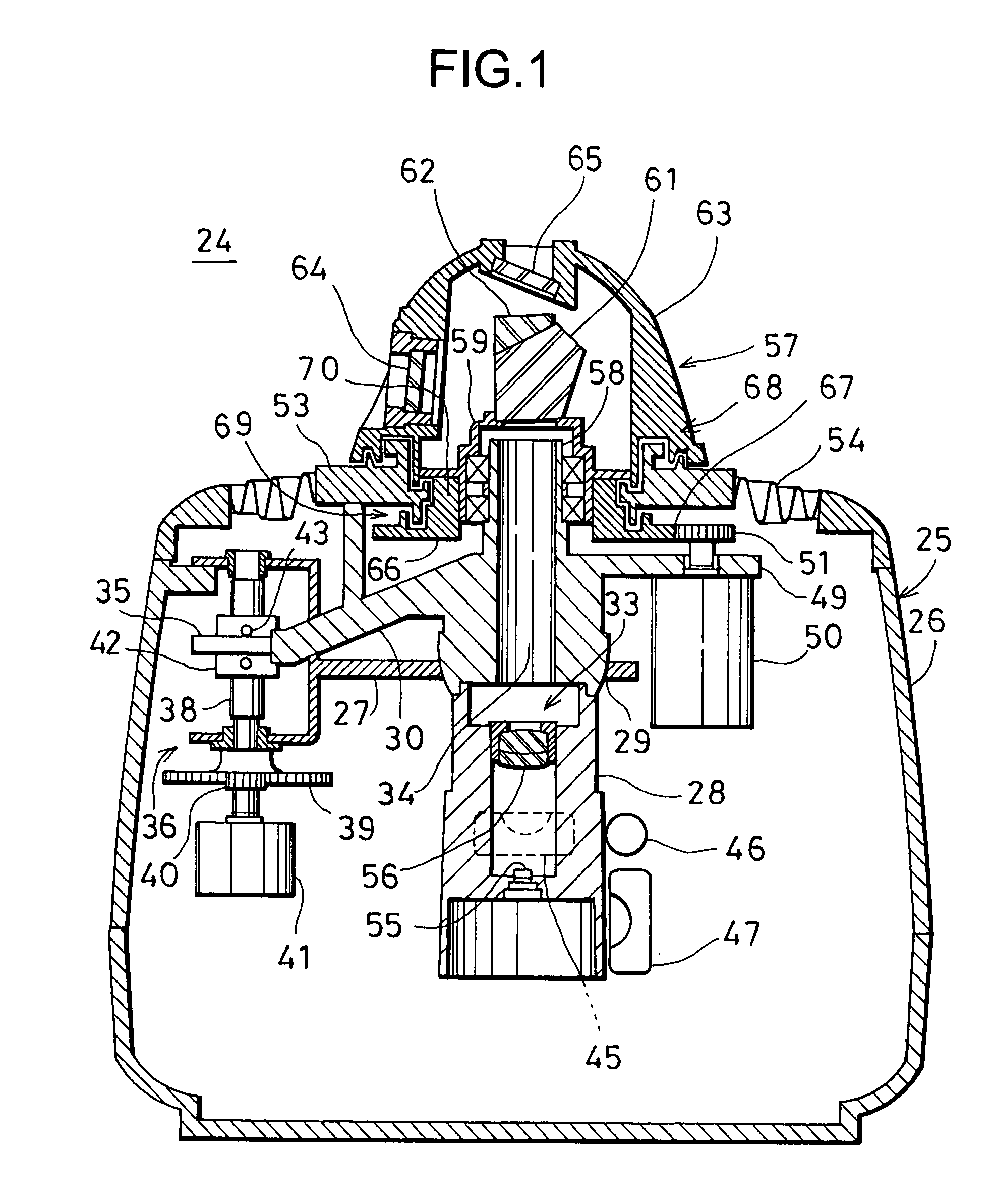
[0087]In the third embodiment, the height of the second annular ridge 72 is h2, and this is higher than the height h1 of the first annular ridge 71. When the surface level of the water staying in the first water trap 81 is increased to higher than the height h1, a pressure by the water staying in the first water trap 81 applies a power to discharge the water to outside, and this prevents the intrusion of the rainwater.

[0088]FIG. 5 shows a fourth embodiment of the invention. In this fourth embodiment, the first annular ridge 71 and the third annular groove 76 are formed in double arrangement. By forming the first annular ridge 71 and the third annular groove 76 in double arrangement, sealing capability up to the first water trap 81 are increased, and water preventing effect as the entire first sealing means 68 can be increased.

[0089]As described above, according to the present invention, non-contact type sealing means can be provided by the crooked and bent route of the gap, and the ...


PUM


Abstract

A laser surveying instrument, comprising a rotating unit for projecting a laser beam by rotary irradiation, a main unit for rotatably supporting the rotating unit, and a sealing means for sealing between the rotating unit and the main unit, wherein the sealing means comprises annular ridges formed on the main unit concentrically to the rotation center of the rotating unit, and annular grooves formed on the rotating unit so that the annular ridges are engaged in the annular grooves and gaps are formed between the annular ridges and the annular grooves, the annular ridges and the annular grooves being arranged concentrically to each other and disposed in double arrangement, and wherein the sealing means further comprises a route bent and crooked in a radial direction by the gaps, and a cavity disposed at least at one point along the route and having larger volume than the volume of the gap.

Description

BACKGROUND OF THE INVENTION[0001]The present invention relates to a laser surveying instrument for projecting a laser beam in rotary irradiation and for forming a reference plane and a reference line. In particular, the present invention relates to a laser surveying instrument with waterproof function.[0002]As a type of laser surveying instrument used for forming a reference plane and a reference line, which are required for operations of civil engineering work, building and construction project, etc. a laser surveying instrument for projecting a laser beam in rotary irradiation is known.[0003]A laser surveying instrument has a rotating unit for deflecting and projecting a laser beam. By rotating the rotating unit, a reference plane or a reference line is formed by the laser beam.[0004]The laser surveying instrument may be used under outdoor conditions, and the laser surveying instrument must have waterproof function so that the laser surveying instrument can also be used under rain...

Claims


Application Information

Patent Timeline
Patent Type & Authority Patents(United States)
IPC IPC(8): G01C15/02
CPCG01C15/004
Inventor HAYASE, SHIN-ICHIHAIJIMA, YASUHITO
Owner KK TOPCON
Why Eureka
Try Eureka