
Electric Oil Pump

a technology of electric oil pump and electric motor, which is applied in the direction of liquid fuel engines, rotary/oscillating piston pump components, machines/engines, etc., can solve the problems of short breakage, and affecting the heat resistance of the oil cooler. , to achieve the effect of improving the heat resistan

Inactive Publication Date: 2016-08-25
HITACHI AUTOMOTIVE SYST LTD
View PDF4 Cites 7 Cited by
  • Summary
  • Abstract
  • Description
  • Claims
  • Application Information

AI Technical Summary

Benefits of technology

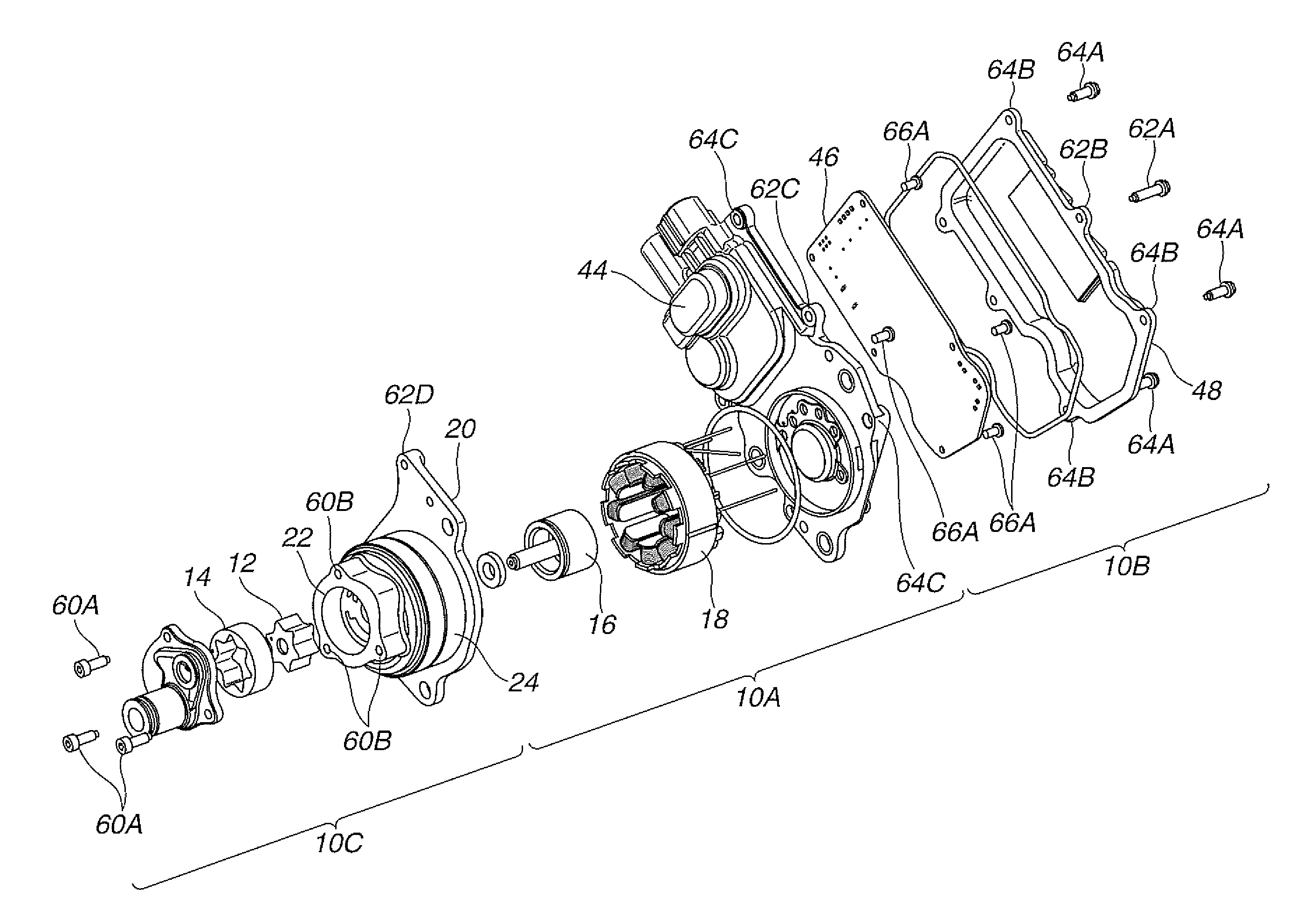
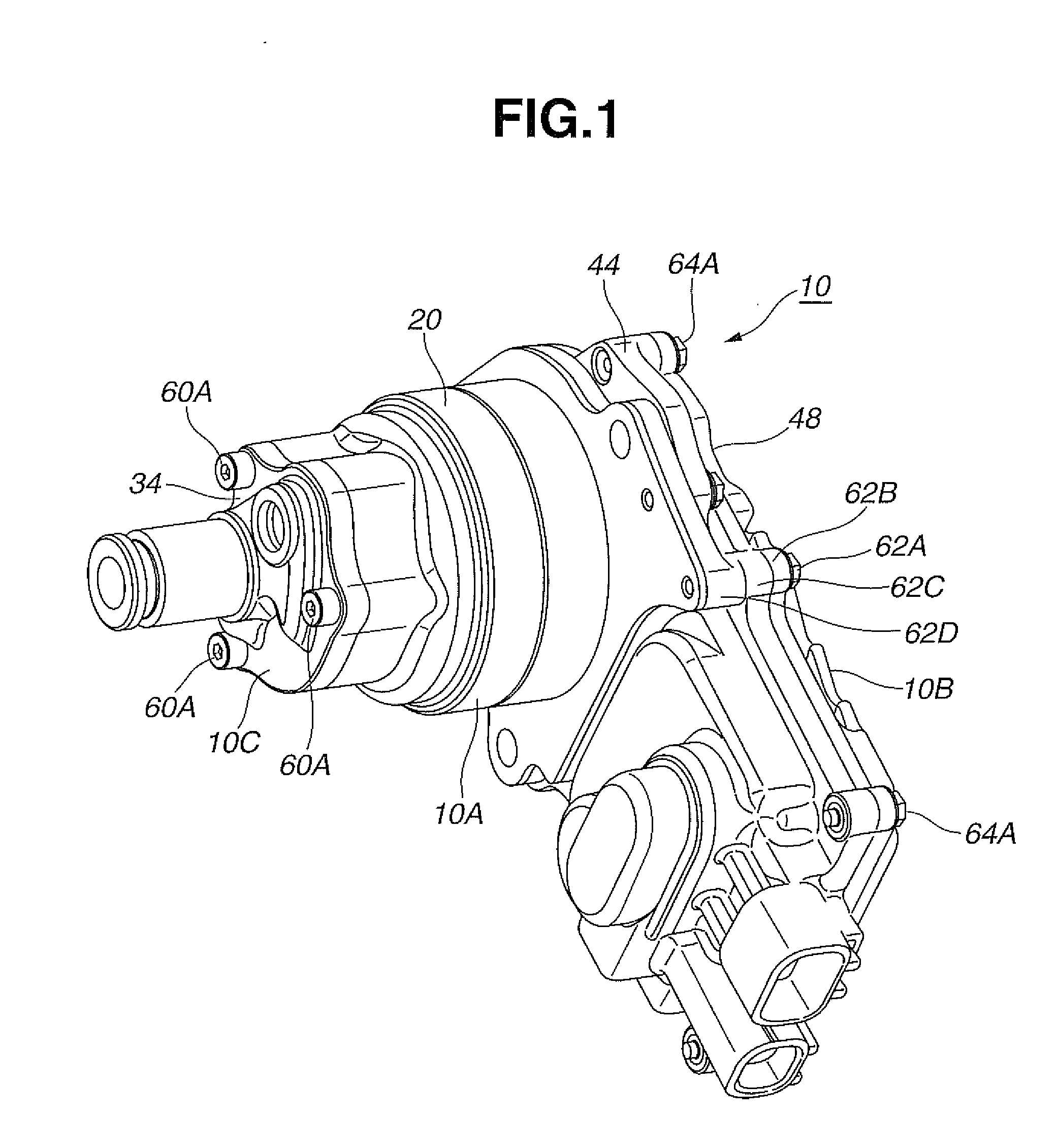
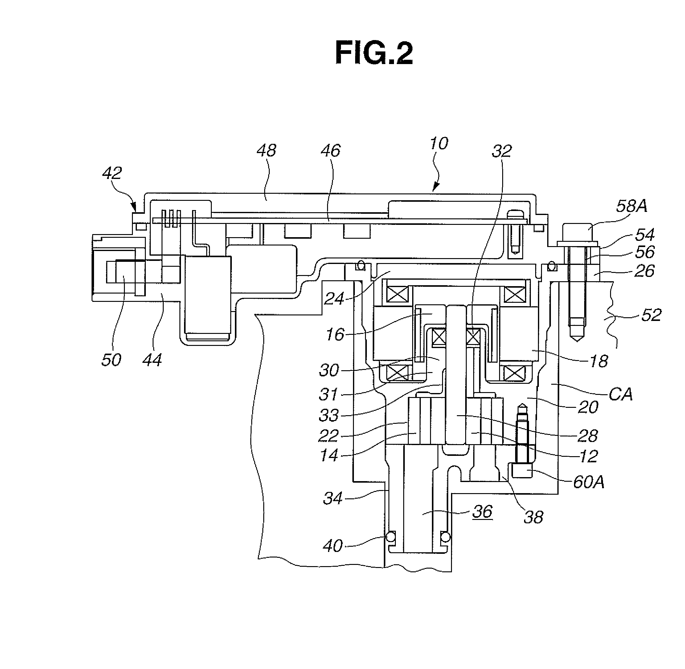
The present invention provides an improved electric oil pump that prevents water intrusion and prevents the heat of hydraulic oil from affecting the control part. The pump has a metal cover and housing, and an oxide film is formed on the outer surface to protect against corrosion. This results in improved heat resistance and protection of the drive control part from the influence of hydraulic oil.

Problems solved by technology

However, drawbacks have been encountered in the above discussed conventional oil cooler.
More specifically, this kind of electric oil pump is usually mounted inside an engine compartment of an automotive vehicle, so that its metal portions are liable to corrosion due to rainwater or saltwater intruding into the engine compartment.
In particular, corrosion tends to develop at a contact surface between a control part case and a control part cover and a contact surface between the control part case and a pump housing thereby allowing the intrusion of rainwater or saltwater also into a space accommodating a control board and into the electric motor part in due course.
Hence there is a fear that the electric element on the control board and the wire in the electric motor part cause a short to be broken down.
For example, if the pump housing is formed of synthetic resin, the synthetic resin is to swell up by the hydraulic oil so that the pump housing cannot keep its functions.
Consequently, there arises a fear that the drive control part cannot be normally operated by the influence of the heat.

Method used


Image

  • Electric Oil Pump
  • Electric Oil Pump
  • Electric Oil Pump

Examples


Embodiment Construction

[0019]Referring now to the accompanying drawings, an embodiment of an electric oil pump according to the present invention will specifically be discussed; however, the invention is not limited to the illustrated embodiment, and modifications and variations of the illustrated embodiment will occur to those skilled in the art.

[0020]An electric oil pump is, for example, a pump to be mounded for automatic transmission of a vehicle having an idle stop function. The automatic transmission refers to a belt-type continuously variable transmission (hereinafter referred to as CVT) equipped separately with a mechanical pump driven by an engine. In the embodiment of the present invention, the electric oil pump is used as a hydraulic pressure supply source for automatic transmission and therefore fixed to a casing for automatic transmission.

[0021]At the time of stopping the engine under an idle stop control, the mechanical pump cannot ensure a hydraulic pressure. Additionally, if a hydraulic pre...


PUM

PropertyMeasurementUnit
driving currentaaaaaaaaaa
corrosion resistanceaaaaaaaaaa
heat resistanceaaaaaaaaaa

Abstract

An electric oil pump is provided to including: (i) a pump part housed in a pump part-accommodating portion formed in a metal pump housing; (ii) an electric motor part housed in an electric motor part-accommodating portion formed in the pump housing; and (iii) a drive control part having (a) a control part case fastened to the pump housing and formed of synthetic resin, (b) a control board for supplying a driving current to the electric motor part, and (c) a metal control part cover fastened to the control part case and accommodating the control board. In this pump, the control part cover and the pump housing are covered with an oxide film having corrosion resistance and heat resistance at least at their outer surface, and the pump housing provided with the oxide film is fixed to an automatic transmission casing in a manner to be immersed in a hydraulic oil.

Description

BACKGROUND OF THE INVENTION[0001]This invention relates to improvements in an electric oil pump, and more particularly to improvements in an electric oil pump where a drive control part which can supply a driving current to an electric motor part for rotating a pump rotor is disposed adjacent to the electric motor part.[0002]In recent years, there have been proposed and developed various idling-stop system equipped vehicles or automatic engine stop-restart system equipped hybrid vehicles for improved fuel economy. In these vehicles, pumps driven by an internal combustion engine are to stop at the time when the internal combustion engine is stopped, and therefore the presence of a pump-driving source other than the internal combustion engine is needed. In particular, the idling-stop system equipped vehicles, automatic engine stop-restart system equipped hybrid vehicles and the like require an oil pump so that a hydraulic mechanism for controlling an automatic transmission can keep en...

Claims


Application Information

Patent Timeline
Patent Type & Authority Applications(United States)
IPC IPC(8): F04C15/00F04C2/10F04C2/08
CPCF04C15/0003F04C15/008F04C2/10F04C2/084F04C15/00F05C2201/021F05C2201/903F05C2253/12F04C2/086F04C2/102F04C13/008F04C15/0096F04C2230/92F04C2240/808F04C2280/04
Inventor CHIKAOKA, TAKAYUKI
Owner HITACHI AUTOMOTIVE SYST LTD
Learn More