Vehicle-side connector

a technology of side connector and vehicle, which is applied in the direction of charging stations, transportation and packaging, and coupling device connection, etc., can solve the problem that the lock plate cannot be mounted on the base portion from above, and achieve the effect of avoiding direct hit by high-pressure water

Active Publication Date: 2016-10-25
SUMITOMO WIRING SYST LTD
View PDF10 Cites 7 Cited by
  • Summary
  • Abstract
  • Description
  • Claims
  • Application Information

AI Technical Summary

Benefits of technology

[0008]According to such a configuration, the locked portion is covered by the lock fitting portion and direct hit of high-pressure water on the locked portion can be avoided by providing the lock fitting portion. Further, since the lock plate is mounted through the mounting hole from behind, it is not necessary to mount the lock plate from above and the lock fitting portion does not stand as a hindrance in mounting the lock plate. Further, since the cover for closing the mounting hole is provided, water intrusion into the interior of the vehicle through the mounting hole can be avoided. Further, in molding the base portion on which the lock plate is to be mounted, a forming mold is inserted through the mounting hole and removed in the front-back direction, whereby the base portion can be molded.
[0013]Generally, a clearance for allowing a smooth movement of the shaft portion is formed between the outer peripheral surface of the shaft portion and the inner peripheral surface of the insertion portion. According to the above configuration, since the above clearance can be covered from front by the water cut-off portion, water intrusion into the above clearance can be prevented at the time of car washing.
[0015]According to such a configuration, water intrusion can be more reliably prevented since the above clearance is closed by the water cut-off portion.
[0019]According to such a configuration, water intrusion into the interior of the vehicle through the mounting hole can be prevented by the seal ring.
[0020]According to the present invention, it is possible to enable the mounting of a lock plate while avoiding direct hit of high-pressure water on a locked portion.

Problems solved by technology

However, if the water cut-off wall is formed, the lock plate cannot be mounted on the base portion from above by being obstructed by the water cut-off wall.

Method used


Image

  • Vehicle-side connector
  • Vehicle-side connector
  • Vehicle-side connector

Examples


Embodiment Construction

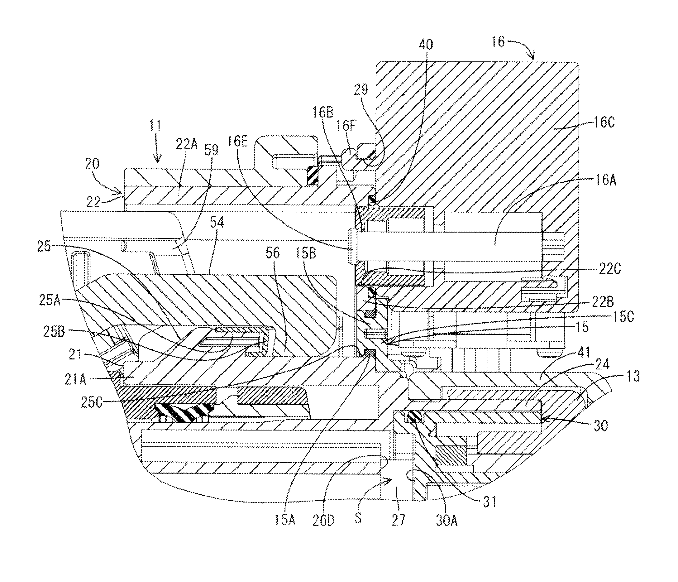
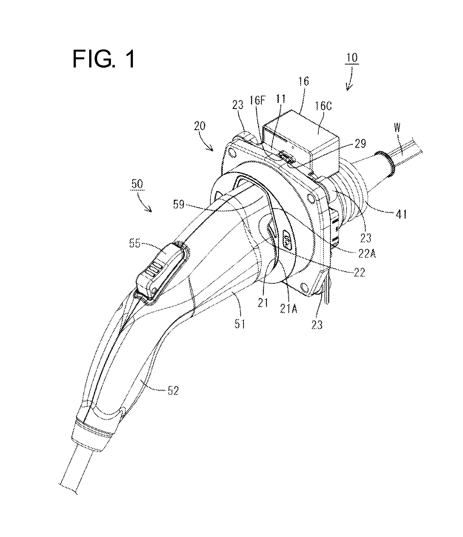
[0035]An embodiment of the present invention is described with reference to FIGS. 1 to 14. A vehicle-side connector 10 of this embodiment is connected to a battery (not shown) mounted in a vehicle via wires W, and a charging connector 50 connected to a charger is connectable thereto from front as shown in FIG. 1. The battery is charged by applying power in a state where the charging connector 50 is properly connected to the vehicle-side connector 10.

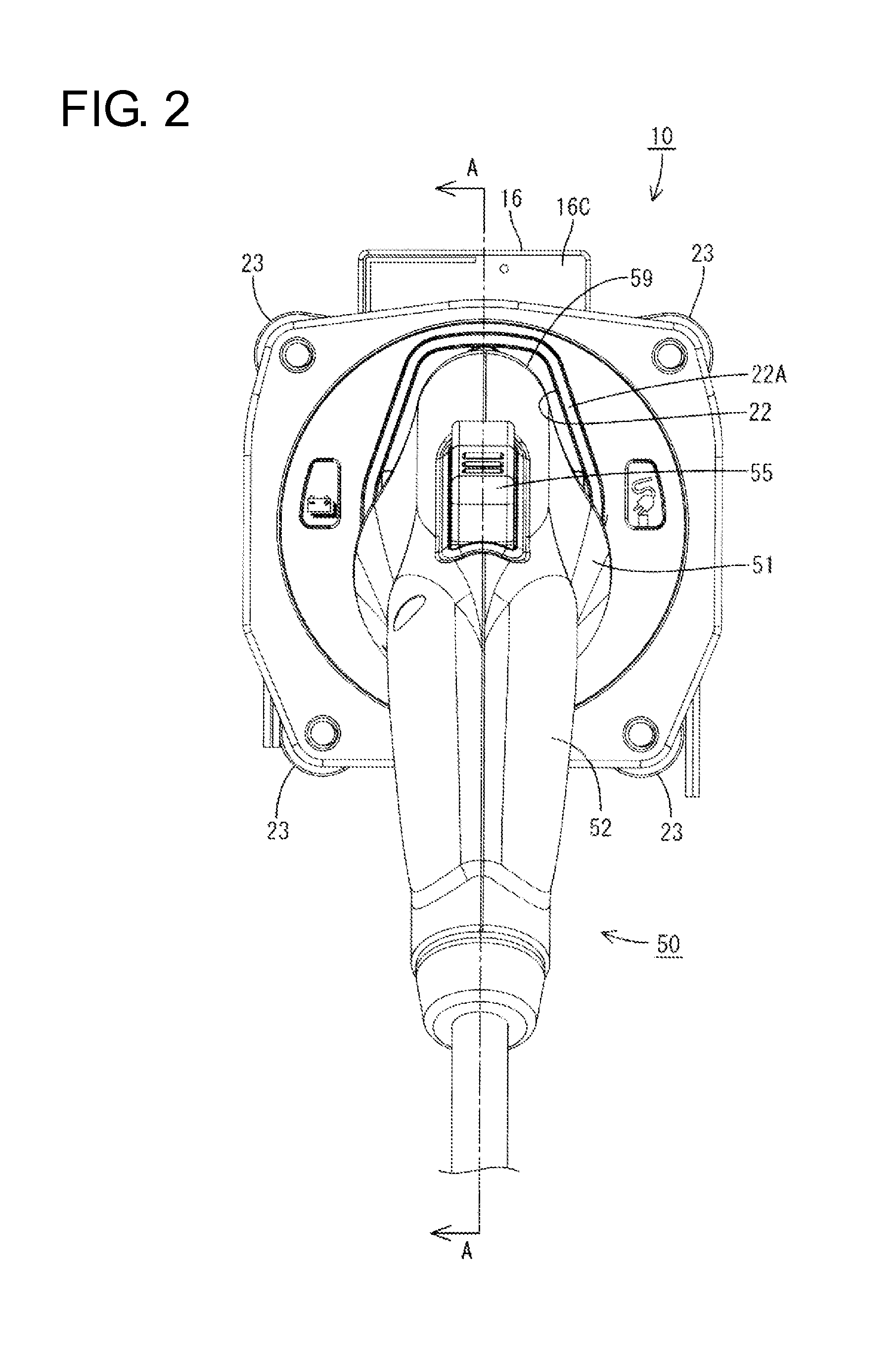
[0036]The charging connector 50 in this embodiment is gun-shaped and includes, as shown in FIG. 1, a connector main body 51 constituting a substantially front half and a grip 52 extending obliquely downward from a rear end part of this connector main body 51. The connector main body 51 and the grip 52 are both made of synthetic resin and integrally molded. As shown in FIG. 9, a hollow cylindrical terminal accommodating tube 53 projecting forward is mounted on the front surface of the connector main body 51. Further, a lock arm 54 is acco...


PUM


Abstract

A vehicle-side connector (10) is connected to a battery mounted in a vehicle and is configured so that a charging connector (50) connected to a charger is connectable thereto from the front. The vehicle-side connector (10) includes a forwardly open lock fitting (22) configured so that a tip part of a lock arm (54) in the charging connector (50) is fit therein from the front. A locked portion (25) in the lock fitting (22) is formed by mounting a metal lock plate (25B) on a base (25A). The lock plate (25B) is made of metal and is configured so that the tip part of the lock arm (54) is to be locked thereto. A mounting hole (25C) for mounting the lock plate (25B) from behind is formed on a back wall (22B) of the lock fitting (22) and a cover (15) is provided to close the mounting hole (25C).

Description

BACKGROUND[0001]1. Field of the Invention[0002]The present invention relates to a vehicle-side connector.[0003]2. Description of the Related Art[0004]A vehicle-side connector to be connected to a battery mounted in a vehicle is known, for example, from Japanese Unexamined Patent Publication No. 2012-221612. This vehicle-side connector includes a hollow cylindrical receptacle into which a charging connector connected to a power supply is connectable. The charging connector is provided with a lock arm and a locking portion is provided on a tip part of this lock arm. A locked portion for holding the two connectors in a connected state by being locked to the locking portion of the lock arm is provided on the upper surface of the receptacle. This locked portion is composed of a lock plate made of metal and a base portion formed on the upper surface of the receptacle, and the lock plate is mounted onto this base portion from above.[0005]High-pressure water is used at the time of car washi...

Claims


Application Information

Patent Timeline
Patent Type & Authority Patents(United States)
IPC IPC(8): H01R13/633H01R13/639B60L11/18H01R13/52H01R13/627
CPCH01R13/633B60L11/1816B60L11/1818H01R13/5227H01R13/6395H01R13/5202H01R13/6275Y02T10/7005Y02T10/7072Y02T90/14B60L53/14B60L53/16Y02T10/70
Inventor SHIMIZU, TOORUMATSUDA, TOSHIYUKI
Owner SUMITOMO WIRING SYST LTD
Why Eureka
Try Eureka