
Device connector

a technology of device connectors and connectors, applied in the direction of coupling device connections, coupling bases/cases, electrical appliances, etc., can solve problems such as water intruders, and achieve the effect of suppressing the pooling of water

Inactive Publication Date: 2017-10-19
AUTONETWORKS TECH LTD +2
View PDF9 Cites 7 Cited by
  • Summary
  • Abstract
  • Description
  • Claims
  • Application Information

AI Technical Summary

Benefits of technology

The invention is about a device connector that prevents water from entering the device when it is detached from its mounting hole. The connector has a water drainage hole that allows any water that enters the connector to be quickly discharged, thereby preventing damage to the seal and ensuring good shielding performance. The water drainage hole can be positioned either above or below the seal and provides a path for water to be quickly discharged. Overall, this invention prevents water from pooling in the shield and ensures the proper functioning of the device connector.

Problems solved by technology

However, if the entire outer surface of the draw-out portion is covered over the entire circumference by the tubular part, water may intrude between the tubular part and the draw-out portion.

Method used


Image

  • Device connector
  • Device connector
  • Device connector

Examples


first embodiment

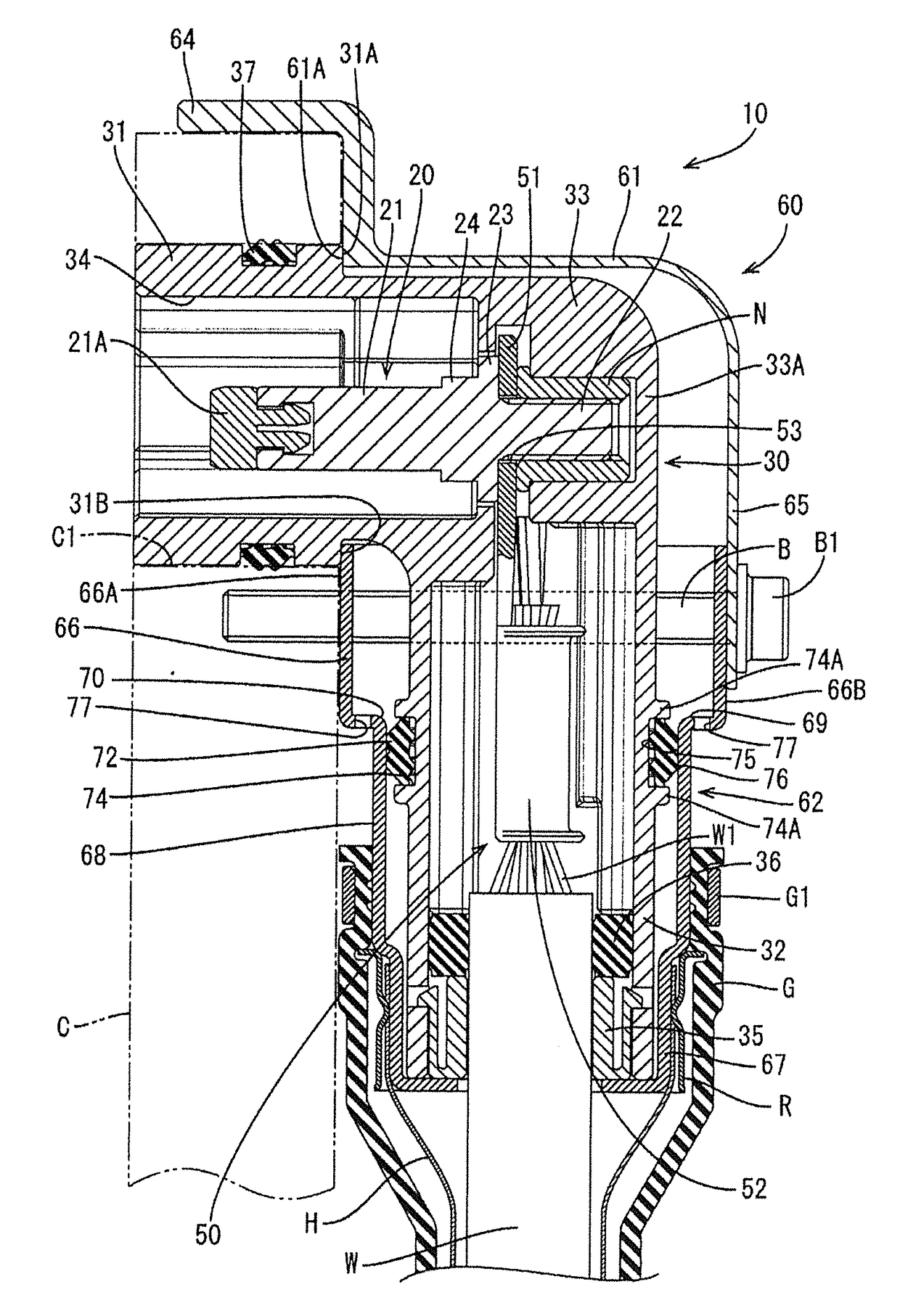
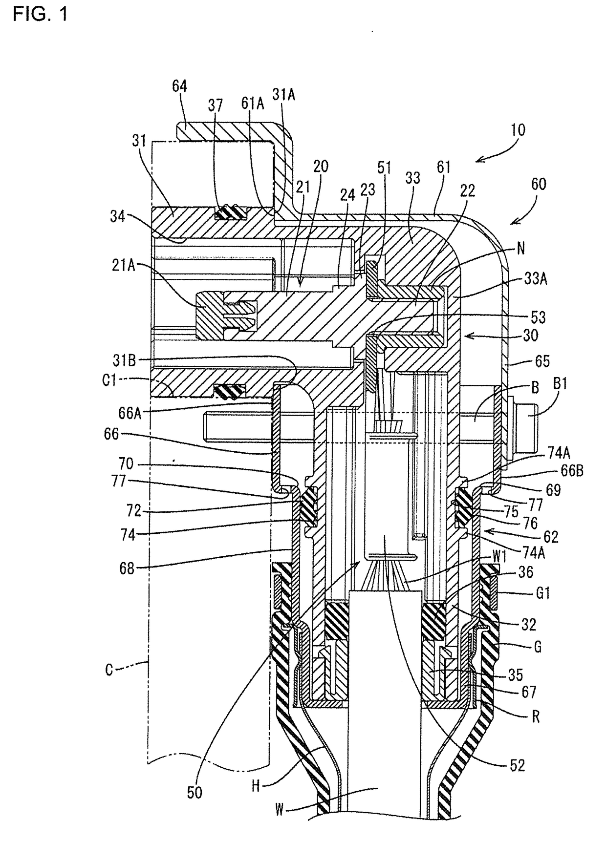
[0016]FIGS. 1 and 2 illustrate a device connector 10 to be mounted into a mounting hole C1 provided on a case C of a device to be installed in a vehicle. Note that, in the following description, a vertical direction is based on FIG. 1. Further, a left side and a right side shown in FIG. 1 are referred to as a front side and a rear side concerning a front-back direction.

[0017]The device connector 10 includes male terminals 20 connectable to unillustrated female terminals of a device-side connector provided in the case C of the device. The device connector 10 also includes a housing 30 made of synthetic resin and configured to accommodate a pair of male terminals 20 arranged in a width direction. Intermediate terminals (an example of a “terminal”) 50 are connected to the male terminals 20 in the housing 30 while being connected to ends of wires W. A shield shell 60 made of metal is configured to cover the housing 30.

[0018]The male terminal 20 is made of metal excellent in conductivity...

second embodiment

[0053]Next, a second embodiment is described with reference to FIG. 3.

[0054]In a device connector 110 of the second embodiment, the positions of the water drainage holes 77 of the lower shell 62 in the first embodiment are changed. Components, functions and effects common to the first embodiment are not repeatedly described. Further, the same reference signs are used to denote the same components as in the first embodiment.

[0055]A water drainage hole 177 of the second embodiment is formed to laterally penetrate through a side wall (an example of the “wall portion”) 66C of an upper shell fitting portion 66 and a lower end opening edge of the water drainage hole 177 is laterally open to be flush with the upper surface of a stepped portion 69. That is, the water drainage hole 177 is provided on a lower end part of the upper shell fitting portion 66 as in the first embodiment. Further, also in this embodiment, a plurality of the water drainage holes 177 are formed to surround a wire int...


PUM


Abstract

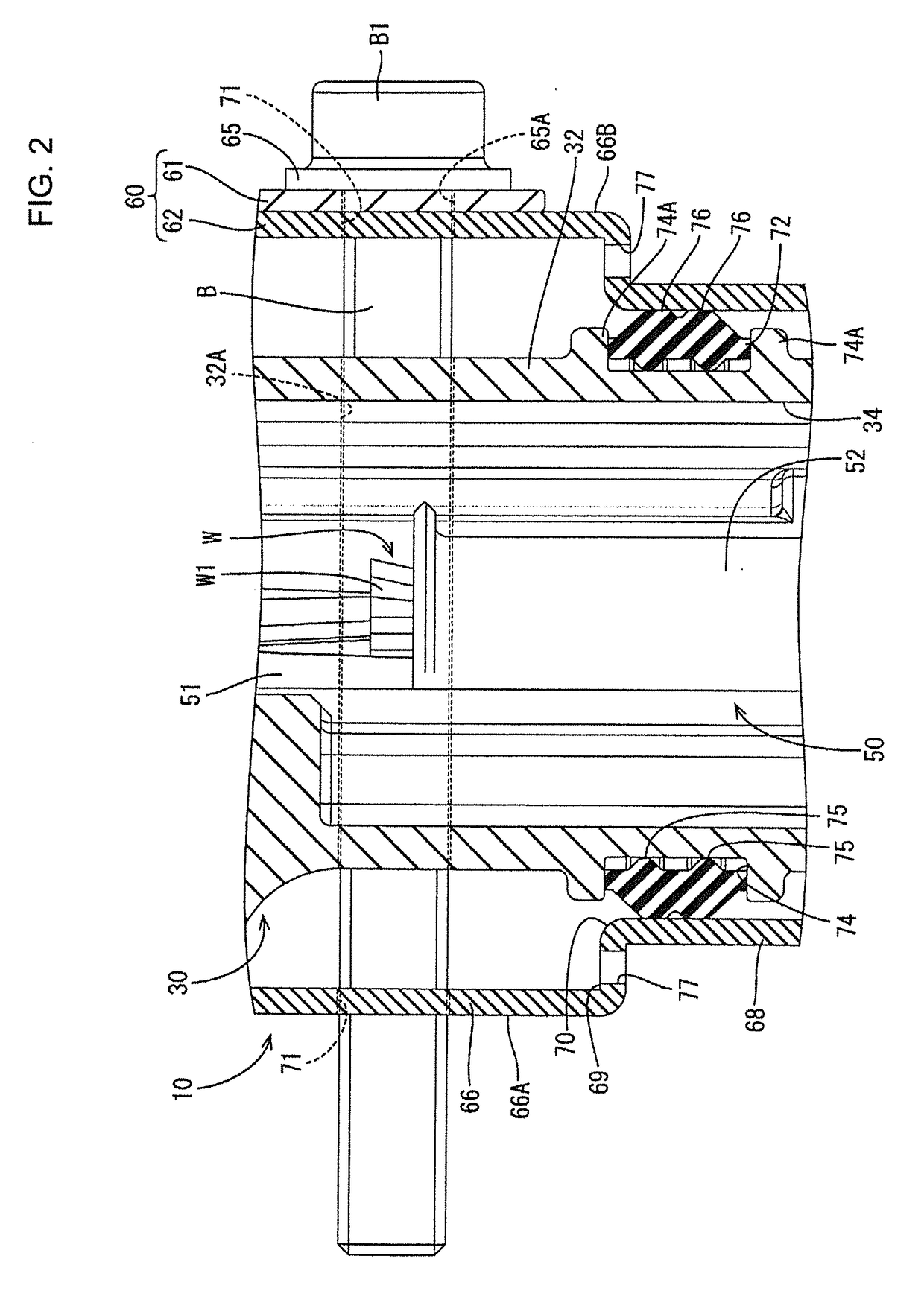
A device connector (10) is mounted into a mounting hole (C1) on a case (C) of a device in a vehicle, and includes terminals (50) connected to wires (W). A synthetic resin housing (30) includes a wire introducing portion (32) and a fitting portion (31). The wire introducing portion (32) receives the wires (W) and the terminals (50) while the fitting portion (31) fits into the mounting hole (C1). A metal shield shell (60) accommodates the wire introducing portion (32) and includes a lower shell (62) for covering the entire outer circumferential surface of the wire introducing portion (32). A seal ring (72) fits on an outer surface of the wire introducing portion (32) and seals between the lower shell (62) and the wire introducing portion (32). Water drainage holes (77) vertically penetrate a stepped portion (69) of the lower shell (62) above the seal ring (72).

Description

BACKGROUND1. Field of the Invention[0001]This specification relates to a device connector.2. Description of the Related Art[0002]Japanese Unexamined Patent Publication No. 2014-107043 discloses a device connector to be mounted into a mounting hole provided on a case of a device to be installed in a vehicleei1073. This device connector includes a housing with a fitting portion provided on a front surface and a shield body. The fitting portion is fittable into a mounting hole of a case and the shield body is to be fixed to the case of the device while covering an outer surface of the housing. The housing is provided with a draw-out portion for pulling out wires in a downward direction intersecting with a fitting direction of the fitting portion. The shield body is fixed to the housing while exposing the front surface of the housing. The device connector is fixed to the case by inserting a bolt through a fixing portion provided on a side surface of the shield body and tightening the bo...

Claims


Application Information

Patent Timeline
IPC IPC(8): H01R13/52
CPCH01R13/5202H01R13/5227H01R13/521H01R13/6581H01R2201/26
Inventor HORIUCHI, KANJIOKUDA, ATSUSHIUEMATSU, NORIYUKITSUJII, YOSHITOMO
Owner AUTONETWORKS TECH LTD
Learn More