Digital intelligent angular travel electric actuator
An electric actuator, intelligent technology, applied in the direction of engine components, valve details, valve operation/release devices, etc., can solve the problems of easy loosening of travel switches, unrealizable, low control accuracy, etc., to increase output torque and stabilize Sexual enhancement, precise control of the effect
- Summary
- Abstract
- Description
- Claims
- Application Information
AI Technical Summary
Problems solved by technology
Method used
Image

Examples
Embodiment 1
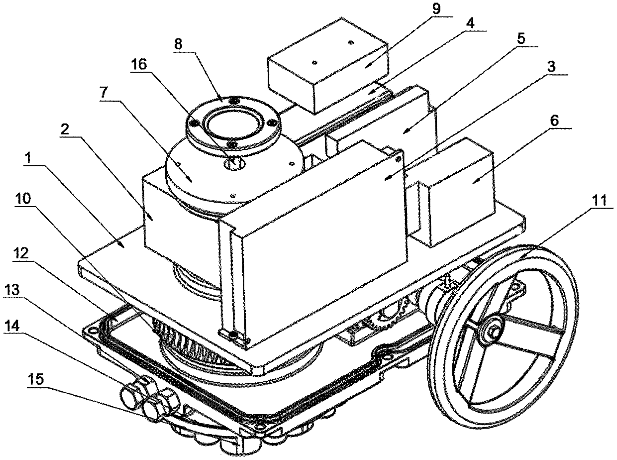
[0024] Such as Figure 1-3 A digital intelligent angular stroke electric actuator shown includes a top plate 1 on which a reducer 2, a power supply module 3, a stepping motor 4, a motor drive controller 5 and a multi-position adjustment module are arranged. 6. The top of the reducer 2 is provided with a control board 7, the top of the control board 7 is provided with a mechanical position display module 8, the top of the stepping motor 4 is provided with a junction box 9, and the bottom of the top board 1 is provided with a manual An integrated transmission mechanism 10 and a handwheel mechanism 11, the bottom of the hand-automatic integrated transmission mechanism 10 is provided with a bottom plate 12, the side wall of the bottom plate 12 is provided with a mechanical limit adjustment mechanism 13, and the bottom of the bottom plate 12 is provided with a connecting flange 14. The bottom of the connecting flange 14 is provided with an output interface 15 .
[0025] Further, t...
Embodiment 2
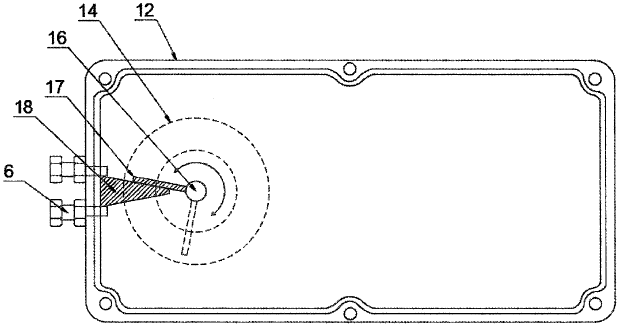
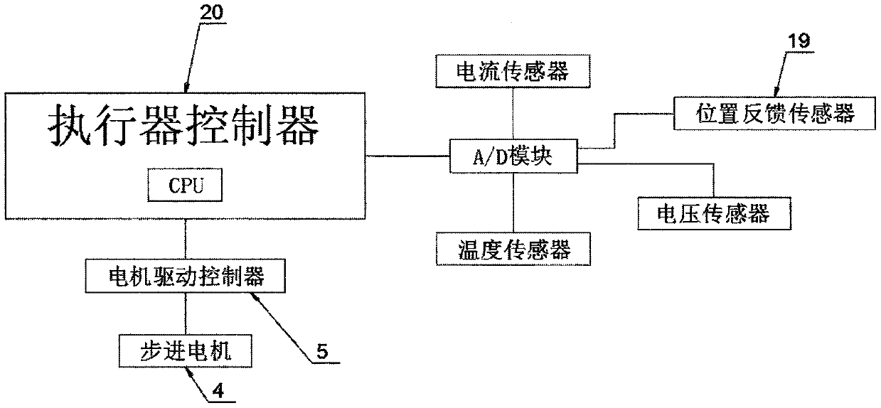
[0033] Such as Figure 1-3 As shown, the connecting flange 14 is connected with the flange on the valve to install the quarter-turn electric actuator, so that the bottom end of the rotating shaft 16 is connected with the valve stem above the valve, and the CPU in the control panel 7 issues a control command to make The angular stroke electric actuator enters the initialization stage, and controls the forward rotation of the stepper motor 4 through the motor drive controller 5, the output shaft of the stepper motor 4 is connected to the reducer 2, and drives the rotating shaft 16 in the reducer 2 to rotate, which will make the valve The valve stem on the top rotates to open the valve. When the limit rod 17 on the rotating shaft 16 moves to the side of the limit baffle 18, the mechanical limit is reached. At this time, the stepping motor 4 is blocked, and the position feedback sensor 19 stops rotating. At this time, no rotation signal is fed back to the CPU in the control board ...
PUM
 Abstract
Description
Claims
Application Information
 - R&D Engineer
- R&D Manager
- IP Professional
- Industry Leading Data Capabilities
- Powerful AI technology
- Patent DNA Extraction
Browse by: Latest US Patents, China's latest patents, Technical Efficacy Thesaurus, Application Domain, Technology Topic.
© 2024 PatSnap. All rights reserved.Legal|Privacy policy|Modern Slavery Act Transparency Statement|Sitemap