A pinlock hardware circuit and electronic equipment

A hardware circuit and judging unit technology, applied in the direction of resource allocation, multi-programming device, concurrent instruction execution, etc., can solve the problems of insufficient spinlock security, complex software control, etc., and achieve high speed, simple software control, and advanced security protection. Effect

Active Publication Date: 2019-06-18
FUZHOU ROCKCHIP SEMICON
6 Cites 0 Cited by

AI-Extracted Technical Summary

Problems solved by technology

[0003] For this reason, it is necessary to provide a spinlock hardware circuit and electronic equipmen...

Abstract

The invention discloses a pinlock hardware circuit and electronic equipment. The hardware circuit comprises a safety protection unit, an address judgment unit, a write data judgment unit, a write-in judgment unit, a read control unit and a spinlock state register unit. wherein the safety protection unit is used for monitoring whether read-write access sent by a bus is safe access sent by a CPU (Central Processing Unit) or not, if the read-write access sent by the bus is safe access, response is given, and if the read-write access sent by the bus is not safe access, an access request of the busis refused; And the address judgment unit is used for inquiring a bus write address, converting the bus write address into selection information corresponding to the to-be-accessed sink register unit, and sending a conversion result to the write data judgment unit and the write judgment unit. According to the technical scheme, a pinlock control algorithm is realized through hardware, and softwarecontrol is simple. And higher-level security protection is realized through security access control at a hardware level. Compared with software control, the speed of hardware control is higher.

Application Domain

Resource allocationConcurrent instruction execution

Technology Topic

Hardware circuitsSpinlock +6

Image

  • A pinlock hardware circuit and electronic equipment
  • A pinlock hardware circuit and electronic equipment

Examples

  • Experimental program(1)

Example Embodiment

[0033] In order to describe in detail the technical content, structural features, achieved objectives and effects of the technical solution, the following detailed descriptions are given in conjunction with specific embodiments and accompanying drawings.
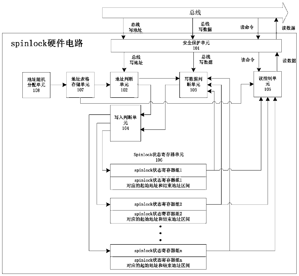
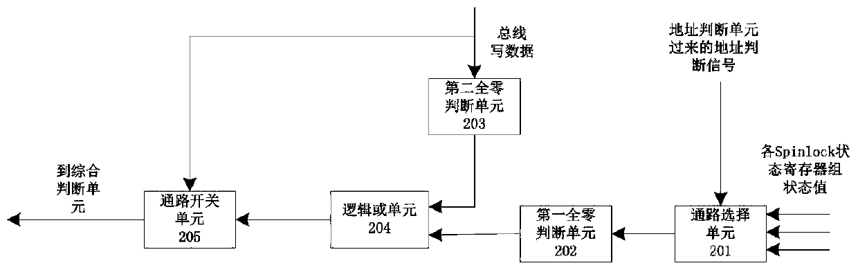
[0034] See Figure 1 to 2 , This embodiment provides a spinlock hardware circuit, including a security protection unit 101, an address determination unit 102, a write data determination unit 103, a write determination unit 104, a read control unit 105, and a spinlock status register unit 106, in which: a security protection unit It is used to monitor whether the read and write access sent by the bus is a safe access issued by the CPU. If it is a safe access, respond, otherwise reject the access request of the bus; the address judgment unit is used to query the write address of the bus and convert the write address of the bus The selection information corresponding to the spinlock register unit to be accessed, and the conversion result is sent to the write data judgment unit and the write judgment unit; the write data judgment unit is used to judge whether the spinlock register needs to be written, and the judgment result is sent To the writing judgment unit; the writing judgment unit writes the spinlock register according to the register unit selection information input by the address judgment unit and the judgment result of whether it can be written and the write data sent by the write data judgment unit; for the spinlock register unit It stores the lock status information of the spinlock and sends the status information to the write data judgment unit and the read control unit; the read control unit is used to perform read operations according to the read command of the bus.
[0035] In the present invention, the safety judgment of the bus command can be realized by the safety protection unit, and the operation of the corresponding spinlock register unit can be realized by the address judgment unit. The write data judging unit and the writing judging unit can realize whether to write control in the spinlock. The spinlock register unit realizes the storage of the lock status information of the spinlock. Through the above-mentioned units, the function of spinlock is realized through hardware and the speed is improved. There is no need to control the software, which is convenient to use. And the safety protection unit is used to monitor whether the read and write access is a safety access issued by the CPU, and will respond only when the access is safe. This can avoid data being compromised when hackers control the CPU to directly access the circuit after hacking the CPU. Only when hackers break through the entrance to the secure world can they issue secure access, which greatly improves the security defense capabilities through the security protection unit.
[0036] For background knowledge of the secure world and the non-secure world, you can refer to the existing public information:
[0037] https://blog.csdn.net/zhouhuacai/article/details/78177364.
[0038] The address of the spinlock register unit of the present application can be directly stored in the address judgment unit, or can be stored in a separate storage unit, the present invention also includes an address table storage unit 107, which is used to store the address of the spinlock register unit for the address judgment unit to perform Inquire.
[0039] In some embodiments, the address of the spinlock register unit may be a fixed address. Or in some embodiments, to improve security, the address is random. The hardware circuit of the present invention also includes an address random allocation unit 108, which is used to randomly allocate the address of the spinlock register unit. The timing of the allocation may be when the circuit is powered on, and the allocated address may be stored in a corresponding storage location, such as the address table storage unit in the foregoing embodiment. In this way, it can be ensured that the physical registers corresponding to the same address are different each time the circuit works, ensuring safety.
[0040] The data writing unit of the present invention is used for judging that the state of the spinlock register is all zeros and the bus write data is all zeros and outputting a signal result that can be written to the writing judging unit. The specific hardware circuit can be implemented as follows: the data writing unit includes a path selection unit 201, a first all-zero determination unit 202, a second all-zero determination unit 203, a logical OR unit 204, and a path switch unit 205, wherein: the path selection unit uses According to the address judgment signal sent by the address judgment unit, the state of the corresponding spinlock register unit is strobed and the state is sent to the all-zero judgment unit; the first all-zero judgment unit is used to judge whether the state of the spinlock register is all zero, and The judgment result is sent to the logic OR unit; all zeros indicate that each bit of the register status is zero. When all zeros are used, the output is yes, and when all zeros are not, the output is no. The second all-zero judgment unit is used to judge whether the bus write data is all zeros, and send the judgment result to the logic OR unit; in the same way, all zeros indicate that every bit is zero, and the output is the result of all zeros. If it is not all zeros, the result is No. The logical OR unit is used to perform logical OR processing on the input two all-zero judgment results, and send the processing results to the path switch unit; if the output result of the logical OR unit is high, that is, one is all zeros, indicating that it can When data is written, the path switch for writing data is turned on. If it is low, it means that data cannot be written, and the path for writing data is closed. This realizes that when the status of the spinlock register is not all zeros, it indicates that the CPU has already used this status register group, so it cannot be written by new data. Only when the state of the spinlock register is all zeros, indicating that the CPU has not used this status register group, the register group can be written with new data. Then when the write data is all zeros, any register group can be cleared.
[0041] The safety protection unit judges whether the access of the bus is safe or not can judge whether the bus command conforms to a preset rule or whether it contains a special signal. If it conforms or contains a special signal, it can be considered safe. Or the prot signal can be judged, and the security protection unit judges the prot signal in the command sent from the bus. If the signal is high, it indicates that the access is a safe access and can be requested accordingly, otherwise the request is not responded and an error flag can be returned.
[0042] In order to realize the storage and corresponding functions of the spinlock information, the register unit includes the spinlock status register group and the corresponding start and end addresses.
[0043] The present invention provides an electronic device, including a spinlock hardware circuit, a bus, and a processor, the processor is connected to the spinlock hardware circuit through the bus, and the spinlock hardware circuit is the aforementioned spinlock hardware circuit. The spinlock hardware circuit of the electronic device realizes the spinlock control algorithm through hardware, and the software control is simple. Realize more advanced security protection through hardware-level security access control. Compared with software control, hardware control is also faster.
[0044] It should be noted that although the foregoing embodiments have been described in this article, the scope of patent protection of the present invention is not limited thereby. Therefore, based on the innovative concept of the present invention, changes and modifications to the embodiments described herein, or equivalent structures or equivalent process transformations made by using the description and drawings of the present invention, directly or indirectly apply the above technical solutions In other related technical fields, they are all included in the scope of patent protection of the present invention.

PUM

no PUM

Description & Claims & Application Information

We can also present the details of the Description, Claims and Application information to help users get a comprehensive understanding of the technical details of the patent, such as background art, summary of invention, brief description of drawings, description of embodiments, and other original content. On the other hand, users can also determine the specific scope of protection of the technology through the list of claims; as well as understand the changes in the life cycle of the technology with the presentation of the patent timeline. Login to view more.

Similar technology patents

Perfusion method for controlling thickness of wax cake

PendingCN113952106ASimple software controlIncrease productivity
Owner:天津市顺博医疗设备有限公司

Method and device for providing voice service

ActiveCN107833574AaccelerateImprove voice service efficiency
Owner:BAIDU ONLINE NETWORK TECH (BEIJIBG) CO LTD +1

Classification and recommendation of technical efficacy words

  • Simple software control

Perfusion method for controlling thickness of wax cake

PendingCN113952106ASimple software controlIncrease productivity
Owner:天津市顺博医疗设备有限公司
Why Eureka
Try Eureka