Urine drainage device

A technology of urine and drainage tanks, which is applied in the field of nursing equipment for the disabled, and can solve the problems of intelligent urination deficiencies, urination into toilets or urinals, urine pollution, etc., and achieve the effect of restoring autonomous urination function

Active Publication Date: 2019-06-21
刘东光
View PDF14 Cites 1 Cited by
  • Summary
  • Abstract
  • Description
  • Claims
  • Application Information

AI Technical Summary

Problems solved by technology

[0003] However, the existing nursing bed-chair transfer system has serious defects in intelligent defecation
It is mainly manifested in the fact that it is difficult for the user to urinate directly into the t

Method used


Image

  • Urine drainage device
  • Urine drainage device
  • Urine drainage device

Examples


Embodiment 1

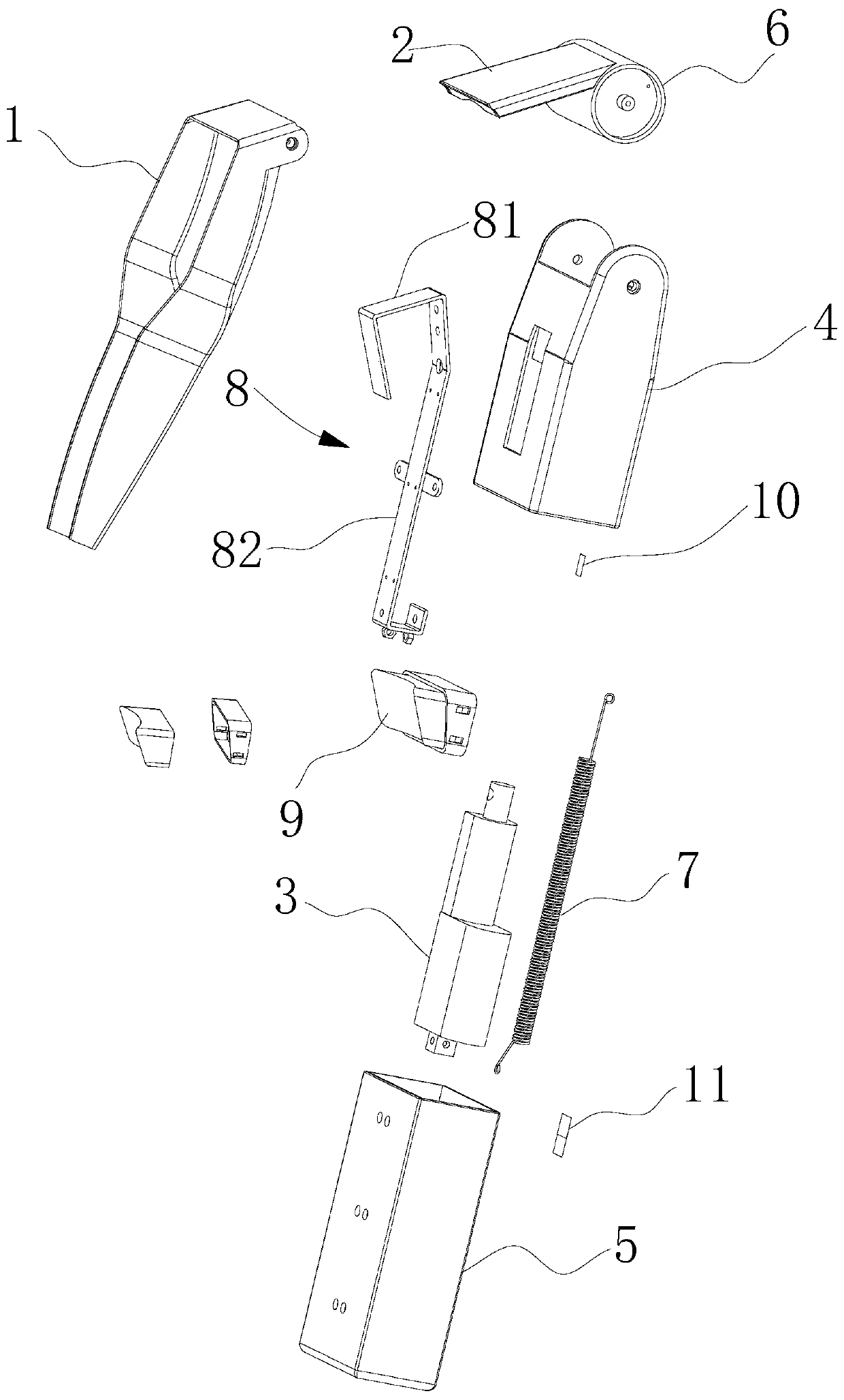
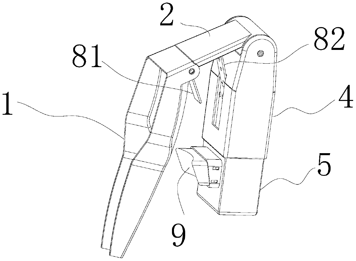
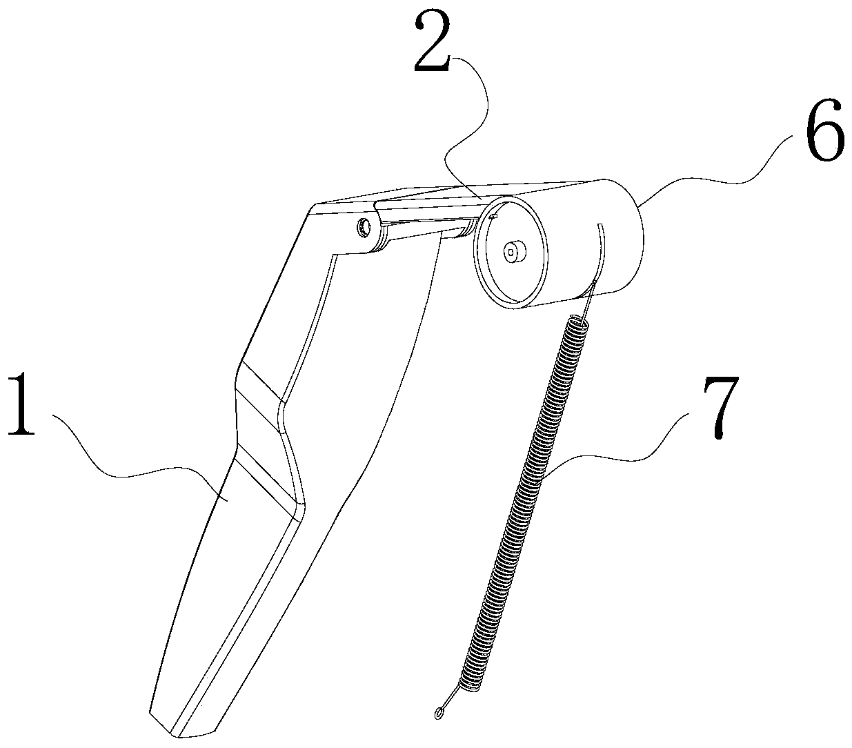
[0026] This embodiment provides a urine drainage device, such as figure 1 As shown in -2, it includes a urine drainage tank 1, a drainage tank lifting rod 2 and a lifting mechanism 3; one end of the drainage tank lifting rod 2 is connected to the urine drainage tank 1, and the other end is connected to the lifting mechanism 3; The urine drainage device also includes an upper connecting sleeve 4 and a lower connecting sleeve 5, the upper connecting sleeve 4 and the lower connecting sleeve 5 are movably socketed; one end of the drainage tank elevating rod 2 is rotatably connected to the The other end of the urine drainage tank 1 is provided with a rotating shaft 6 , and the rotating shaft 6 is axially and rotatably connected to the upper connecting sleeve 4 ; the lifting mechanism 3 is connected to the rotating shaft 6 .

[0027] In the above-mentioned urine drainage device, by setting the two ends of the lifting rod of the drainage tank to be rotatably connected to the urine dr...

Embodiment 2

[0038] This embodiment provides a method for utilizing the urine drainage device described in Embodiment 1, comprising the following steps:

[0039] S1. Extend the urine drainage groove into the urine collection mechanism (such as toilet, urinal, etc.), such as Image 6 As shown; when the patient needs to defecate, the lifting mechanism is started, and the lifting mechanism drives the rotation shaft to rotate, thereby driving one end of the lifting rod of the drainage tank to rotate upward, driving the urine drainage tank to move upward;

[0040] S2. The position after the upward movement of the urine drainage groove corresponds to the position of the toilet hole of the wheelchair in the bed-chair transfer system with toilet holes, and drains the patient's urine into the urine collection mechanism;

[0041] S3. After the patient finishes defecation, the electric push rod is controlled to start, and the rotating shaft is driven to rotate in the opposite direction, thereby drivi...


PUM


Abstract

The invention discloses a urine drainage device. The urine drainage device comprises a urine drainage groove, a drainage groove ascending and descending rod and an ascending and descending mechanism,wherein one end of the drainage groove ascending and descending rod is connected to the urine drainage groove, and the other end is connected with the ascending and descending mechanism; the urine drainage device also comprises an upper connecting sleeve and a lower connecting sleeve; the upper connecting sleeve and the lower connecting sleeve are in sleeve connection movably; one end of the drainage groove ascending and descending rod is rotatablely connected to the urine drainage groove, and the other end is provided with a rotating shaft; the rotating shaft is connected to the upper connecting sleeve in a way of being rotatable in an axial direction; and the ascending and descending mechanism is connected to the rotating shaft. The urine drainage device disclosed by the invention can bemounted on an ordinary closestool and can be connected with wheel chair vehicles of most bed-chair transfer systems with defecation holes, so that a user can independently and naturally complete theprocess of urinating to a urinal on an existing nursing wheelchair with the defecation hole. The urine drainage device disclosed by the invention has far-reaching significance on helping disabled people recover the independent urination function, and creating intelligent old-age equipment and intelligent sickrooms.

Description

technical field [0001] The invention relates to nursing equipment for disabled persons, in particular to a urine drainage device. Background technique [0002] At present, the nursing bed-chair transfer system is used to transfer paralyzed or bedridden patients, the elderly, etc. from the bed to the wheelchair, and then take it to the toilet, bathroom, etc., so as to resume getting on and off the bed, walking indoors, going to the toilet, and taking a bath It will have a huge impact on the development of smart elderly care and smart wards. [0003] However, the existing nursing bed-chair transfer system has serious defects in intelligent defecation. It is mainly manifested in the fact that it is difficult for the user to urinate directly into the toilet or urinal due to the influence of the posture of the user in the wheelchair, and the discharged urination is easy to spill a large amount on the chair cushion near the defecation hole, causing urine pollution. In fact, no m...

Claims


Application Information

Patent Timeline
IPC IPC(8): A47K11/04
Inventor 刘东光
Owner 刘东光
Why Eureka
Try Eureka