

Self-adaptive rocket spray tube applied to rocket based combined circulating engine
An engine and self-adaptive technology, applied in the field of power system, can solve problems such as complex structure, difficult heat protection, high manufacturing cost, etc., to achieve the effect of improving overall performance, improving anti-back pressure ability, and reducing weight
- Summary
- Abstract
- Description
- Claims
- Application Information
AI Technical Summary
Problems solved by technology
Method used
Image


Examples
Embodiment Construction
[0021] In order to make the object, technical solution and advantages of the present invention clearer, the present invention will be further described in detail below in conjunction with the accompanying drawings and embodiments. It should be understood that the specific embodiments described here are only used to explain the present invention, not to limit the present invention.
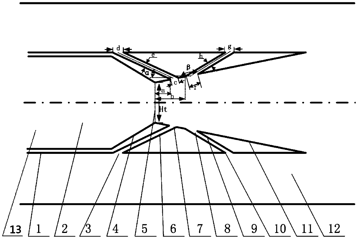
[0022] Using the design idea of the present invention to carry out two-dimensional pulling up, according to the design requirements of the engine, a binary self-adaptive rocket nozzle applied to a rocket-based combined cycle engine can be designed. By axisymmetrically arranging the suction channel and the aerodynamic tab channel, the axisymmetric adaptive rocket nozzle applied to the rocket-based combined cycle engine can be designed.
[0023] refer to figure 1 , is applied to an adaptive rocket nozzle of a rocket-based combined cycle engine, and the adaptive rocket nozzle is located in the engi...
PUM
 Abstract
Description
Claims
Application Information