
Negative pressure self-suction type fluid dead cavity destruction device

A self-priming, negative pressure technology, used in gas/liquid distribution and storage, pipeline systems, mechanical equipment, etc., can solve the problem of bypass dead space, which cannot be solved well, the fluid resistance of the main pipeline increases, and the fluid flow rate changes. Slow and other problems, to achieve the effect of consistent temperature change, large fluid suction, and fast flow rate

Pending Publication Date: 2019-07-12
WUHAN QICHENG BIOLOGICAL TECH
View PDF0 Cites 0 Cited by
  • Summary
  • Abstract
  • Description
  • Claims
  • Application Information

AI Technical Summary

Problems solved by technology

[0002] There are a large number of unavoidable bypass dead spaces other than the main pipeline in the water purification treatment systems or other fluid pipeline systems used in various industries on the market, which cannot be solved well
Some people even install control valves or thinner pipelines on the main fluid pipeline to increase the resistance at both ends of the pipeline to form a pressure difference. Through the pressure drop, the fluid is pressed into the branch pipeline and then returned to the main pipeline to realize the flow of fluid bypass. method, the above method has the following defects: there is a bypass dead space or the flow rate of the fluid in the bypass becomes slow; the flow rate of the pipeline is small and the fluid resistance of the main pipeline increases

Method used


Image

  • Negative pressure self-suction type fluid dead cavity destruction device
  • Negative pressure self-suction type fluid dead cavity destruction device
  • Negative pressure self-suction type fluid dead cavity destruction device

Examples


Embodiment Construction

[0021] The principles and features of the present invention are described below in conjunction with the accompanying drawings, and the examples given are only used to explain the present invention, and are not intended to limit the scope of the present invention.

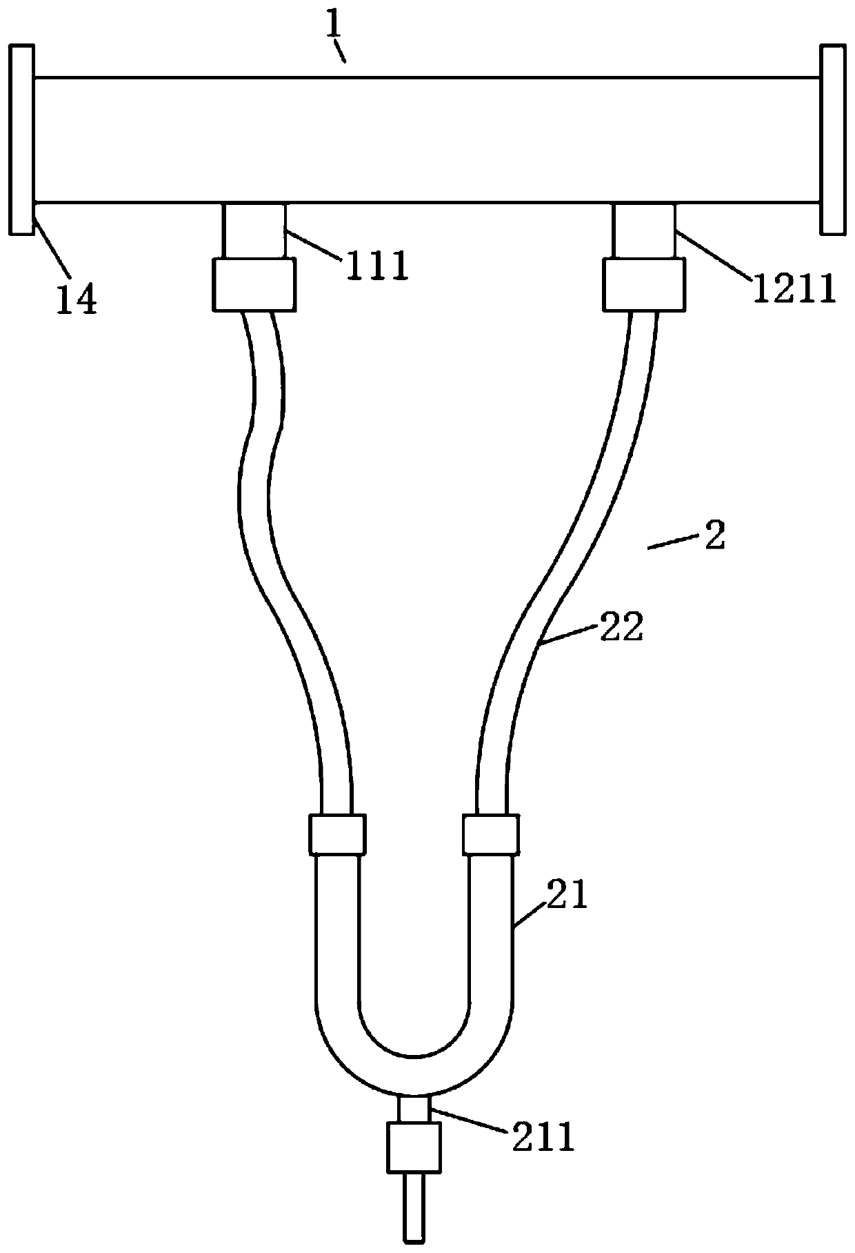
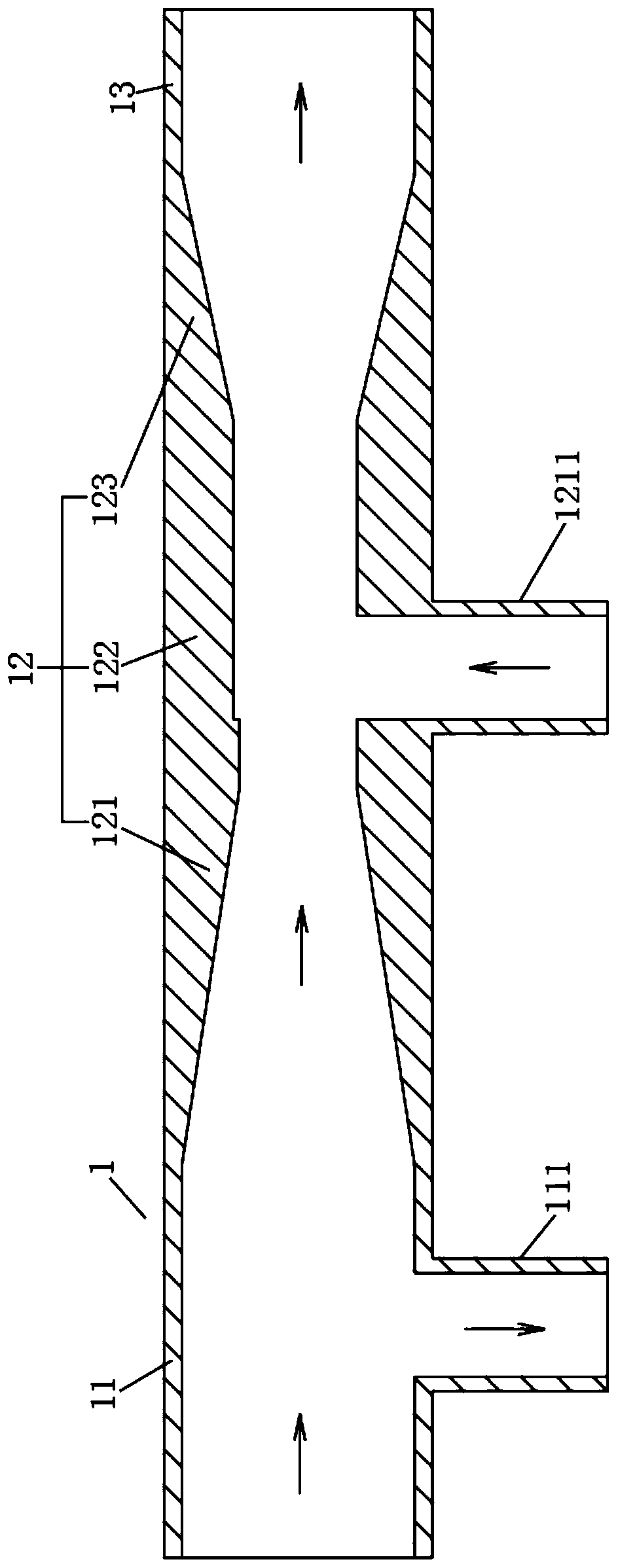
[0022] Example: such as figure 1 and 2 As shown, the negative pressure self-priming fluid dead space breaking device of this embodiment includes a main pipeline 1 and a bypass pipeline 2. The above-mentioned main pipeline 1 includes an advection inlet section 11 that is continuously arranged and communicated from front to back along its fluid flow direction. , the jet section 12 and the flat outlet section 13, the above-mentioned advection inlet section 11 is communicated with a bypass outlet nozzle 111, and the above-mentioned jet section 12 is communicated with a bypass suction nozzle 1211, and the above-mentioned jet section 12 is used to increase fluid flow velocity and pressure, and form a negative pressure at...


PUM


Abstract

The invention relates to a negative pressure self-suction type fluid dead cavity destruction device. The device comprises a main pipeline and a bypass branch pipeline; the main pipeline comprises a horizontal inflow section, a jet section and a flat flow outlet section which are sequentially and continuously arranged from front to back and are in communicated with the main pipeline in the fluid flowing direction of the main pipeline; the horizontal flow inlet section is in communication with a bypass lead-out pipe opening, the jet section is in communication with a bypass suction pipe opening,and the jet section is used for increasing the flow rate and the pressure of the fluid and a negative pressure is formed at the position of the bypass suction pipe opening; and the bypass pipeline isarranged the bypass lead-out pipe opening and the bypass suction pipe opening in a communicating mode, the bypass pipeline is in communication with a use point water outlet, and a valve used for controlling the flow of the use point water outlet is arranged at the use point water outlet. The device has the advantages that the structure design is reasonable, the dead cavity phenomenon of the bypass pipeline can be effectively improved, the inner fluid suction force of the bypass pipeline is increase, the flow rate is large, the flow speed is high, no dead cavity of the pipeline is completely achieved, and the temperature changes of the main pipeline and the bypass temperature are consistent.

Description

technical field [0001] The invention relates to the technical field of pipeline fluids, in particular to a negative pressure self-priming fluid dead space destruction device. Background technique [0002] There are a large number of unavoidable bypass dead spaces other than the main pipeline in the water purification treatment systems or other fluid pipeline systems used in various industries on the market, which cannot be solved well. Some people even install control valves or thinner pipelines on the main fluid pipeline to increase the resistance at both ends of the pipeline to form a pressure difference. Through the pressure drop, the fluid is pressed into the branch pipeline and returned to the main pipeline to realize the fluid flow of the bypass fluid. method, the above method has the following defects: there is a bypass dead space or the flow rate of the fluid in the bypass becomes slow; the flow rate of the pipeline is small and the fluid resistance of the main pipel...

Claims


Application Information

Patent Timeline
Patent Type & Authority Applications(China)
IPC IPC(8): F17D3/01
CPCF17D3/01
Inventor 张小军阮安
Owner WUHAN QICHENG BIOLOGICAL TECH
Learn More