
Jet swirl air blast fuel injector for gas turbine engine

一种燃料喷射器、燃气涡轮的技术,应用在涡轮/推进燃料输送系统、发动机元件、机器/发动机等方向,能够解决不充分混合、性能和操作、涡破裂、不利TVC或轴向分级燃烧器性能和操作等问题

Active Publication Date: 2019-07-16
GENERAL ELECTRIC CO
View PDF3 Cites 1 Cited by
  • Summary
  • Abstract
  • Description
  • Claims
  • Application Information

AI Technical Summary

Problems solved by technology

Although this performance attribute is recognized or preferred in conventional lean- or rich-burn annular, can or can-annular combustor assemblies, this attribute can lead to vortex breakup, centerline reverse flow, and generally insufficient mixing , performance and operation, which are detrimental to TVC or axially staged combustor performance and operation

Method used


Image

  • Jet swirl air blast fuel injector for gas turbine engine
  • Jet swirl air blast fuel injector for gas turbine engine
  • Jet swirl air blast fuel injector for gas turbine engine

Examples


Embodiment Construction

[0165] Reference will now be made in detail to embodiments of the invention, one or more examples of which are illustrated in the accompanying drawings. Each example is provided by way of explanation of the invention, not limitation of the invention. In fact, it will be apparent to those skilled in the art that various modifications and variations can be made in the present invention without departing from the scope or spirit of the invention. For example, features illustrated or described as part of one embodiment can be used with another embodiment to yield a still further embodiment. Thus, it is intended that the present invention covers such modifications and variations as come within the scope of the appended claims and their equivalents.

[0166] As used herein, the terms "first," "second," and "third" are used interchangeably to distinguish one element from another, and are not intended to denote the position or importance of individual elements.

[0167] The terms "u...


PUM


Abstract

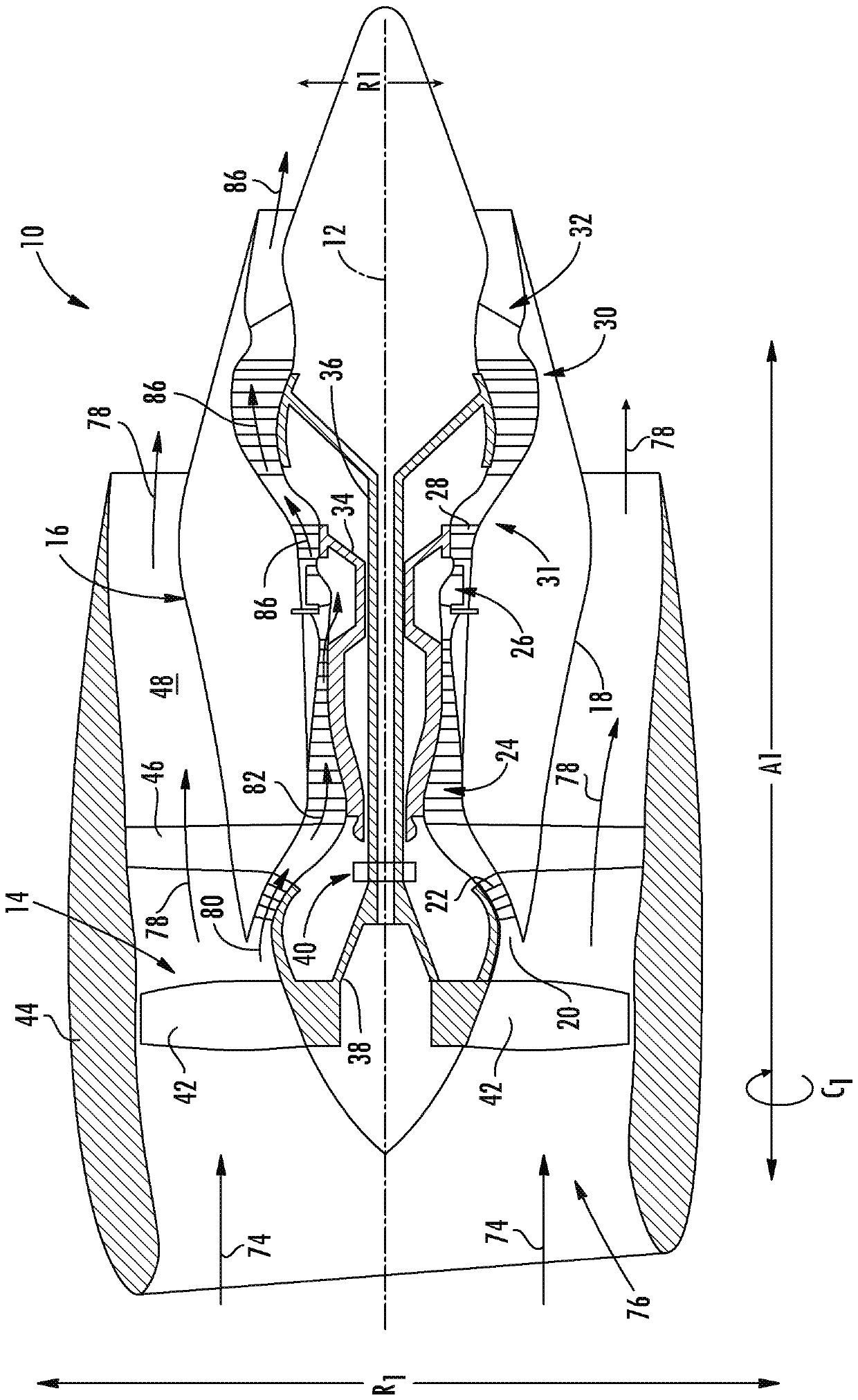
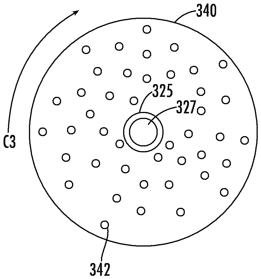
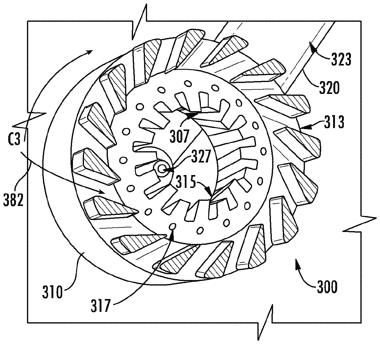
A fuel injector for a gas turbine engine includes an outer sleeve. An upstream end of the outer sleeve defines an inlet opening and a downstream end defines an exit opening, each of which defined within the outer sleeve. The outer sleeve defines a radial opening extended therethrough along the radial direction. At least a portion of the outer sleeve defines a plurality of grooves. The outer sleevedefines a fuel conduit through at least a portion of the outer sleeve outward of the plurality of grooves along the radial direction from the fuel injector centerline. The fuel conduit defines a fuelinjection opening inward along the radial direction of the radial opening defined through the outer sleeve. A first member of an arm is coupled to the outer sleeve. A second member of the arm is contoured defining a fuel injection port generally concentric to the fuel injector centerline.

Description

technical field [0001] The subject matter generally relates to fuel injectors for combustion assemblies. Background technique [0002] Gas turbine engines, and particularly their combustion components, are increasingly challenged with regard to reducing emissions, increasing power output, and improving performance and operability, including at part load or part power conditions. However, the weight and space that can be allocated to combustion components in a gas turbine engine is limited. [0003] Potential solutions for improving emissions output, power output and / or performance and operability are trapped vortex combustors (TVC) or axially staged combustor assemblies. However, known fuel injectors generally produce high swirl (eg, swirl numbers of about 0.5 or greater) or relatively low axial swirl of the fuel or fuel / oxidizer mixture when applied to TVC or axially staged combustors. Vector momentum flow. Still further, known fuel injectors generally include one or mor...

Claims


Application Information

Patent Timeline
Patent Type & Authority Applications(China)
IPC IPC(8): F23R3/28F23R3/34F23R3/10
CPCF23R3/10F23R3/28F23R3/286F23R3/34F23R3/283F23R3/346F23R3/36F23R3/58F23R2900/00015F23R3/60F02C7/22F05D2240/35F23R3/20F23R3/14
Inventor G.A.博德曼J.M.马蒂尼M.A.本杰明P.奈克
Owner GENERAL ELECTRIC CO
Features
  • Generate Ideas
  • Intellectual Property
  • Life Sciences
  • Materials
  • Tech Scout
  • Unparalleled Data Quality
  • Higher Quality Content
  • 60% Fewer Hallucinations
Learn More