A 10kv cable joint protection device

A technology for cable joints and protection devices, applied in cable joints, fire rescue and other directions, can solve problems such as damage to cable joints and damage expansion, and achieve the effect of reducing impact, being less susceptible, and less prone to electromagnetic interference.

Active Publication Date: 2020-04-17
ANHUI YIFALA ELECTRICAL CO LTD
View PDF10 Cites 0 Cited by
  • Summary
  • Abstract
  • Description
  • Claims
  • Application Information

AI Technical Summary

Problems solved by technology

[0005] The purpose of the present invention is to provide a 10KV cable joint protection device to solve the problem in the prior art that multiple cable joints arranged in the same underground cable shaft will damage other cable joints due to the explosion of one cable joint, resulting in rapid damage expansion.

Method used


Image

  • A 10kv cable joint protection device
  • A 10kv cable joint protection device
  • A 10kv cable joint protection device

Examples


Embodiment 1

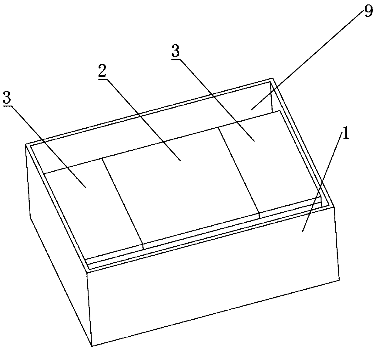
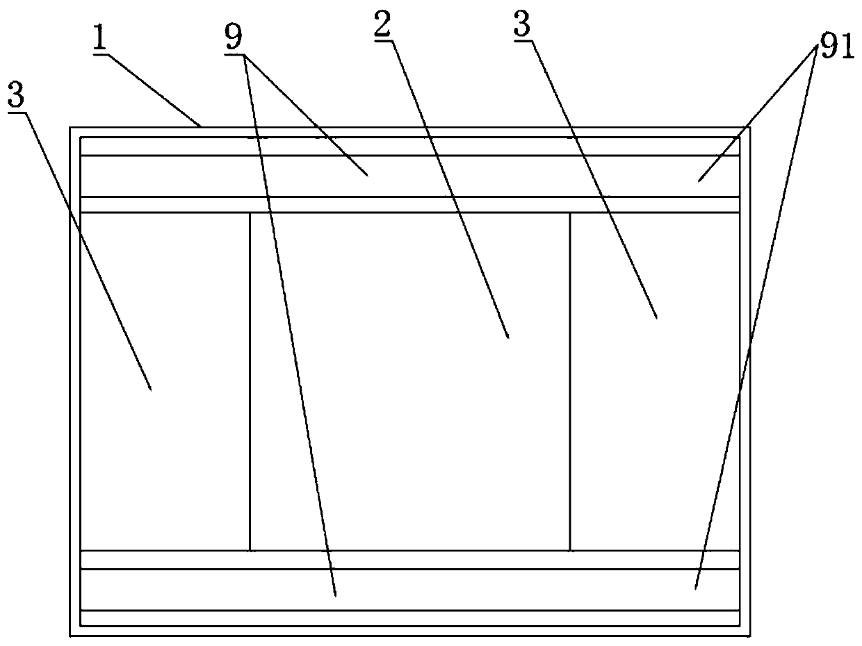
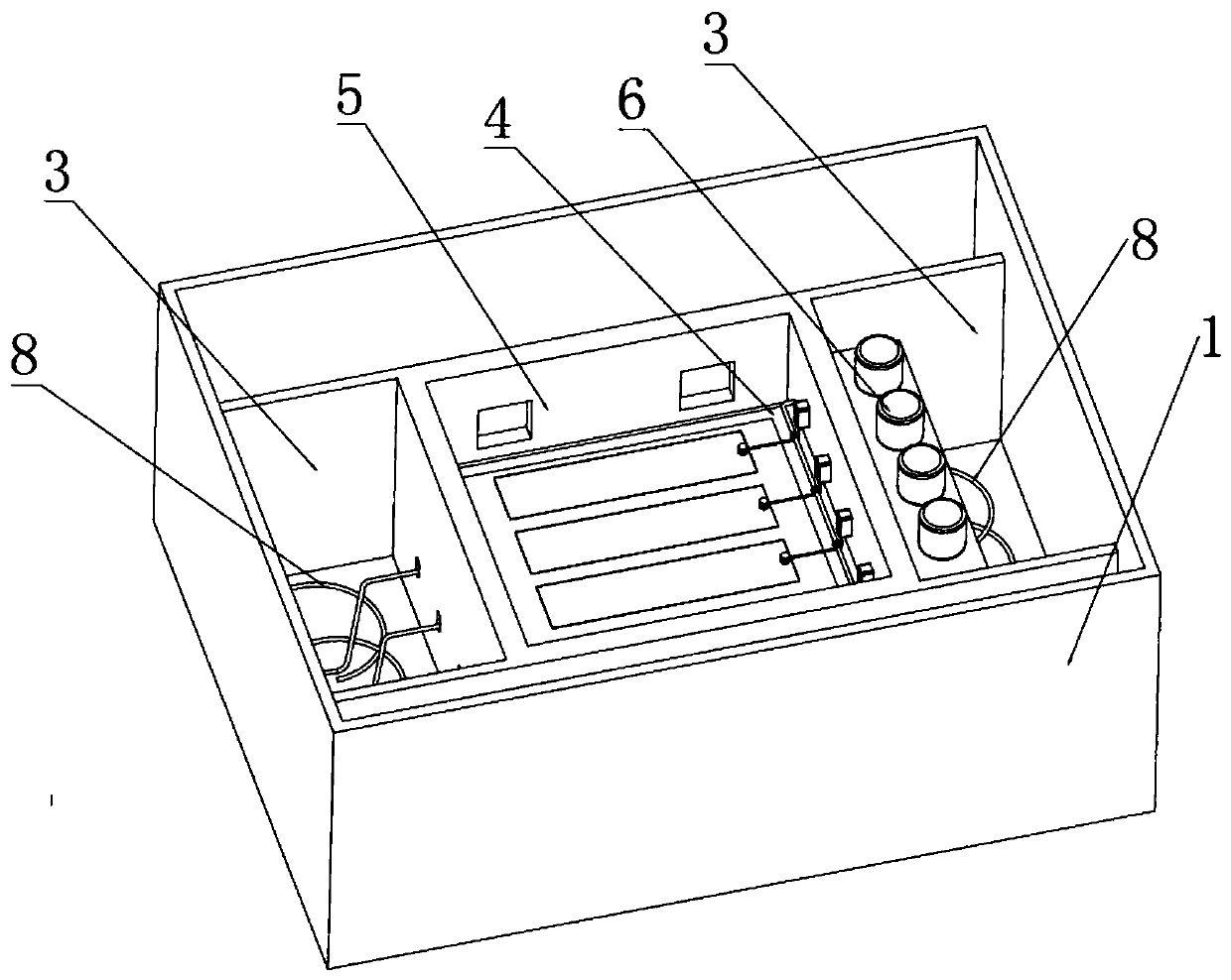
[0038] Such as Figure 1-12 As shown, the present invention provides a 10KV cable joint protection device in this embodiment, including an explosion-proof box 7 arranged outside each cable joint, and one side of the explosion-proof box 7 is provided with an energy release hole 71, and the cable joint There are more than one. The 10KV cable joint protection device also includes an outer casing 1 embedded in the soil body, a partition structure and an explosion suppression device 6 arranged in the outer casing 1 .

[0039] The partition structure divides the outer casing 1 longitudinally into three transverse cavities, the lateral cavities on both sides are the side cavities 9 and the middle one is the cable connection cavity 2 . The cable connection chamber 2 is divided into cable accommodation chambers 3 located at both ends and an intermediate chamber located in the middle by the partition structure. The intermediate chamber is divided into upper and lower layers, and the lo...


PUM


Abstract

The invention discloses a 10KV cable joint protecting device. The device comprises a shell body buried in a soil body, a partition plate structure arranged in the shell body and an explosion suppression device; a cable connecting cavity is formed in the shell body; the cable connecting cavity is transversely divided into two cable containing cavities and a middle cavity located in the middle by the partition plate structure; the middle cavity is divided into an upper layer and a lower layer; the lower layer of the middle cavity is a joint protection box and is uniformly divided into a plurality of joint protection sub-cavities in the longitudinal direction; the upper layer of the middle cavity is an explosion-proof cavity; sub-cavity openings which communicate with the joint protection sub-cavities in a one-to-one correspondence mode are formed in a joint protection cover; each sub-cavity opening is connected with a sub-cavity cover through a spigot structure in a covered mode; the bottom of each sub-cavity cover is provided with an explosion-proof box through a joint connecting frame; and an energy release hole is downward. Through the explosion-proof cavity, the impact generatedby explosion is effectively reduced, and a cable joint is prevented from damaging the side walls of the joint protection sub-cavities to damage an adjacent cable joint.

Description

technical field [0001] The invention relates to a cable joint protection device, in particular to a 10KV cable joint protection device. Background technique [0002] High-voltage cables are generally long, and often need to be laid in a segmented connection. At the segmented connection, cables are connected with cable joints. Cable joints are a high incidence of faults, so protection measures must be taken for high-voltage cable joints, and the fewer cable joints, the better. For the protection of cable joints, underground cable wells are generally used for protection at present, and underground cable wells are set at the cable joints, so as to facilitate the protection of underground cables and future maintenance and repair. [0003] When the cable well protects the cable joint, the cable joint is covered with an explosion-proof box. One side of the explosion-proof box is generally provided with a pressure relief hole. After the explosion-proof box is closed and sealed, th...

Claims


Application Information

Patent Timeline
Patent Type & Authority Patents(China)
IPC IPC(8): H02G15/10A62C3/16
CPCA62C3/16H02G15/10
Inventor 戴文忠戴章吴钰娟戴超戴玉
Owner ANHUI YIFALA ELECTRICAL CO LTD
Why Eureka
Try Eureka