


Quick Research
Generate reliable direction feasibility study reports for your R&D in just a few steps.

Technical Q&A
Discover and master advanced knowledge NOW. Basics, ideas, possibilities, all at once.

Find Solutions
As an expert in R&D theories, this can generate solutions to your technical problems instantly.

Evaluate Feasibility
Analyze your overall solution with one click, know your potential R&D risks in advance.

Monitor Landscape
Get weekly tech updates, stay abreast of the latest tech innovations and key insights.
New energy vehicle kinetic energy recovery wheel hub built-in generator
A new energy vehicle and kinetic energy recovery technology, which is applied to electric vehicles, auxiliary drive devices, power management, etc., can solve the problems of long charging time, consumption, and high cost, and achieve the effect of increasing the ultra-long cruising range
- Summary
- Abstract
- Description
- Claims
- Application Information
AI Technical Summary
Problems solved by technology
Method used
Image

Examples
Embodiment 1
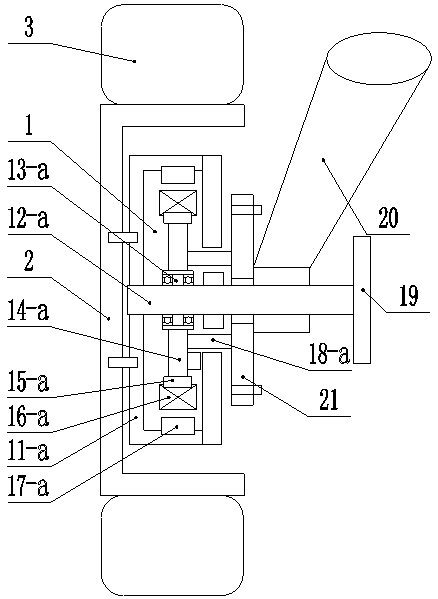
[0035] like figure 1 As shown, the generator 1 in the present invention includes a first housing 11-a, a first inner shaft 12-a, a first bearing 13-a, a first frame 14-a, and a first stator 15-a , the first coil 16-a, the first rotor magnetic steel 17-a, the connecting pipe 18-a, the brake disc 19 and the connecting disc 21, the first housing 11-a is an inner hollow cylindrical box with an opening on one side Body, the unopened side of the first shell 11-a is fixedly connected with the hub 2 by screws, the first inner shaft 12-a is fixedly installed in the first shell 11-a, and the first inner shaft 12-a The first disc frame 14-a is installed through the first bearing 13-a, the outer edge of the first disc frame 14-a is fixedly installed with the first stator 15-a, and the first stator 15-a is coiled with the first A coil 16-a, the first rotor magnetic steel 17-a is fixedly installed in the middle of the inner surface of the first housing 11-a corresponding to the position of...
Embodiment 2
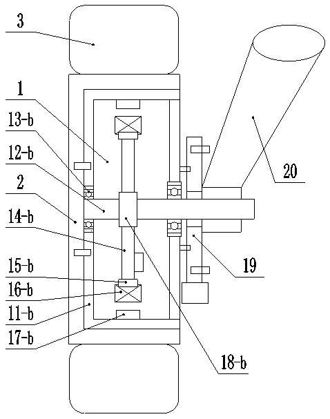
[0038] like figure 2 As shown, the generator 1 in the present invention includes a second housing 11-b, a second inner shaft 12-b, a second bearing 13-b, a second frame 14-b, a second stator 15-b, The second coil 16-b, the second rotor magnetic steel 17-b, the second shaft sleeve 18-b and the brake disc 19, the second housing 11-b is an inner hollow cylindrical box, the second housing 11- b is fixedly connected with the wheel hub 2 through screws, and the second inner shaft 12-b is installed in the second housing 11-b, and both ends of the second inner shaft 12-b are connected to the second housing through the second bearing 13-b. The housing wall of the body 11-b is connected and one end thereof protrudes from the outside of the second housing 11-b. The second inner shaft 12-b is equipped with a second disc frame 14-b through a second bushing 18-b. The second shaft sleeve 18 is set on the second inner shaft 12-b through a key connection, and the outer edge of the second fra...
Embodiment 3
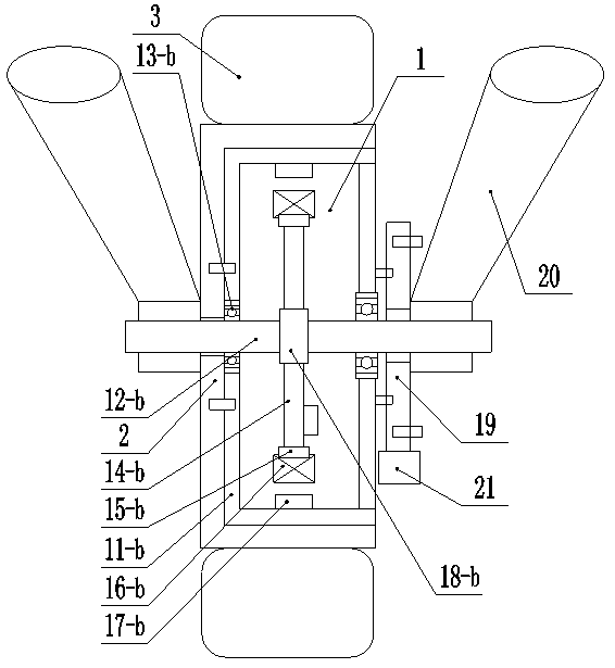
[0041] like image 3 As shown, on the basis of the third embodiment, the end of the second inner shaft 12 - b close to the hub 2 penetrates to the outside of the hub 2 and is connected to the vehicle body through the shock absorber 20 . This structure is suitable for electric vehicles with two or three wheels, so that both sides of the hub 2 are fixedly connected with the vehicle body.
PUM
 Abstract
Description
Claims
Application Information
 - R&D Engineer
- R&D Manager
- IP Professional
- Industry Leading Data Capabilities
- Powerful AI technology
- Patent DNA Extraction
Browse by: Latest US Patents, China's latest patents, Technical Efficacy Thesaurus, Application Domain, Technology Topic, Popular Technical Reports.
© 2024 PatSnap. All rights reserved.Legal|Privacy policy|Modern Slavery Act Transparency Statement|Sitemap|About US| Contact US: help@patsnap.com