

Glass defect detection method based on reflective structured light illumination
A structured light illumination and defect detection technology, which is applied to measuring devices, material analysis through optical means, instruments, etc., can solve problems such as inability to obtain high-contrast defect images, inability to realize area array detection, weak scattered light intensity, etc., to achieve Avoid lighting verification tests, improve defect detection efficiency, and enhance the effect of defects
- Summary
- Abstract
- Description
- Claims
- Application Information
AI Technical Summary
Problems solved by technology
Method used
Image


Examples
Embodiment 1
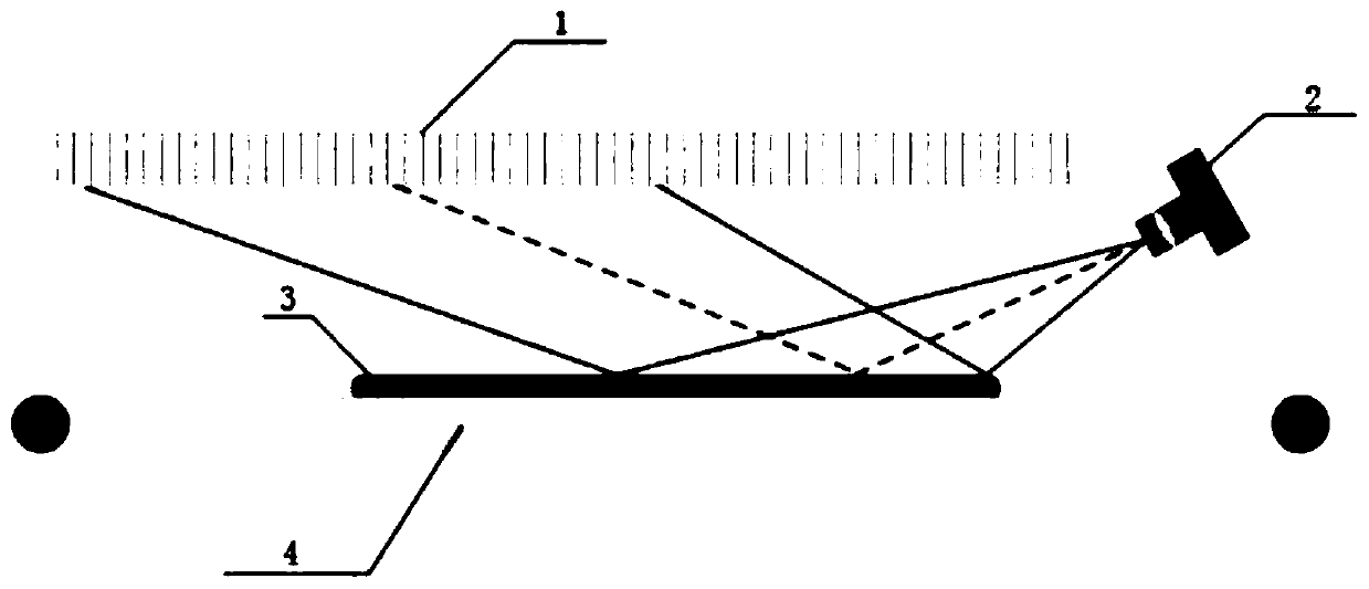
[0030] Such as figure 1 , image 3 , Figure 4 Shown, the present invention comprises the steps:
[0031] S1. The structured light source is generated by the liquid crystal display 1. Both the imaging module 2 and the liquid crystal display 1 are placed 200 mm above the glass sample 3 to be inspected. The liquid crystal display 1 displays sinusoidal structural stripes as a structured light illumination source. The glass sample 3 to be inspected Placed on the motion scanning mechanism 4; the motion scanning mechanism 4 can use a conveyor;
[0032] S2. The imaging module 2 is installed obliquely above the glass sample 3 to be inspected, and the lens of the imaging module 2 is adjusted so that the glass sample 3 to be inspected is clearly imaged;
[0033] S3. The liquid crystal display 1 displays images of different phases to control the translation of the display stripes. The structured light stripes are translated 4 times, and each translation distance is 1 / 4 of the period o...
Embodiment 2
[0045] Such as Figure 2 ~ Figure 4 As shown, the fringe projection module 5 projects sinusoidal stripes on the surface of the ground glass screen 6 as a structured light illumination source. The ground glass screen 6 is placed 200 mm above the glass sample 3 to be inspected, and the imaging module 2 is installed on the glass sample 3 to be inspected. Obliquely above, the glass sample 3 to be inspected is placed on the belt conveying mechanism 4, the stripe projection module 5 is located above the frosted glass screen 6, the lens used in the imaging module 2 is a Sham lens, and the object plane of the lens is exactly located on the glass sample to be inspected 3 surface, the Sham angle of the lens can be adjusted to adapt to different object working distances; the fringe projection module 5 projects fringe images of different phases to control the translation of the displayed fringes, each shifting 1 / 4 of the fringe cycle, Then the imaging module 2 collects 4 times to obtain 4...
PUM
 Abstract
Description
Claims
Application Information