
LED dimming circuit, dimming device and dimming method for improving dimming precision

A dimming accuracy and dimming circuit technology, applied in the LED field, can solve the problems of complex circuit structure and increased implementation cost, and achieve the effect of simplifying the circuit structure, reducing cost, and improving LED dimming accuracy

Pending Publication Date: 2019-07-19
SHENZHEN SHENDIE SEMICON
View PDF0 Cites 1 Cited by
  • Summary
  • Abstract
  • Description
  • Claims
  • Application Information

AI Technical Summary

Problems solved by technology

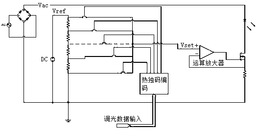
[0002] The output of the LED drive power supply is a constant current source, and different power supply values ​​correspond to the brightness of different light sources, such as figure 1 As shown, LED dimming is achieved by changing the reference voltage Vset of the constant current source, and the reference voltage Vset comes from different taps of the resistor string. When the dimming accuracy increases by 1 bit, the number of resistors, the number of switches and the decoding The circuit will be doubled, that is, assuming the original binary 6bit dimming precision, there are a total of 64 levels of brightness in the dimming circuit, 63 resistances are all R resistors R1~R63 connected in series, and 64 switches K0~K63, If the accuracy is increased to 8bit, the traditional method requires 255 resistors and 256 switches, making the circuit structure complex and greatly increasing the implementation cost

Method used


Image

  • LED dimming circuit, dimming device and dimming method for improving dimming precision
  • LED dimming circuit, dimming device and dimming method for improving dimming precision
  • LED dimming circuit, dimming device and dimming method for improving dimming precision

Examples


Embodiment Construction

[0028] The object of the present invention is to provide an LED dimming circuit, a dimming device and a dimming method that improve the dimming precision. The design of a simple circuit structure can greatly improve the LED dimming precision, simplify the circuit structure, and reduce the cost of implementation. the cost of.

[0029] In order to make the object, technical solution and effect of the present invention more clear and definite, the present invention will be further described in detail below with reference to the accompanying drawings and examples. It should be understood that the specific embodiments described here are only used to explain the present invention, not to limit the present invention.

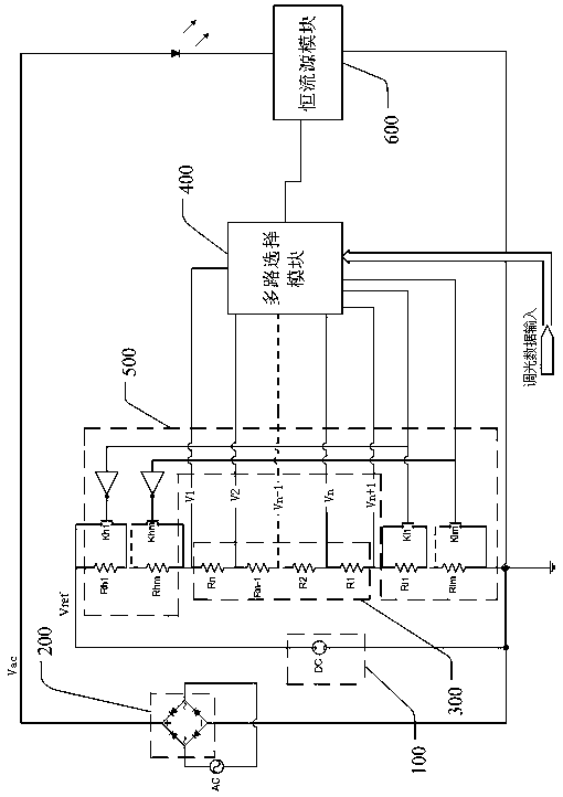
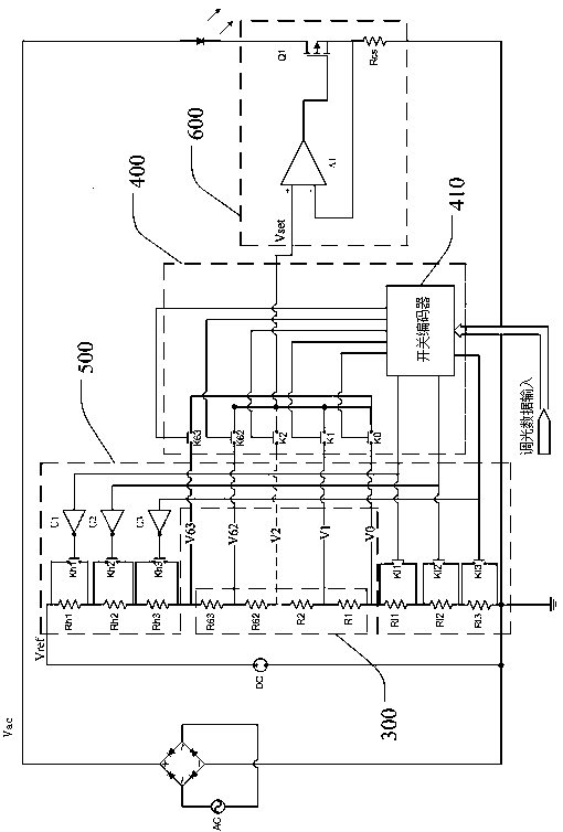
[0030] see figure 2, the LED dimming circuit with improved dimming accuracy provided by the present invention is connected to the LED lamp string, including a DC stabilized power supply 100, a rectifier module 200, a voltage divider module 300, a multi-channel select...


PUM


Abstract

The invention discloses an LED dimming circuit, a dimming device and a dimming method for improving the dimming precision, wherein the LED dimming circuit for improving the dimming precision comprisesa voltage dividing module, a multi-path selection module, an adjusting module and a constant-current source module, wherein the voltage dividing module is used for dividing the reference voltage output by a direct-current voltage-stabilizing power supply, and outputting the corresponding voltage signals to the multi-path selection module through different taps; the multi-path selection module outputs a control signal to the adjusting module according to the received dimming data, and outputs the voltage signals output by the voltage dividing module corresponding to the taps to the constant-current source module; and the adjusting module is used for adjusting the values of the voltage signals output corresponding to the taps according to the control signal, and the constant-current sourcemodule controls the current flowing through an LED lamp string according to the current received voltage signal. By means of the design of the simple circuit structure, the LED dimming precision can be effectively improved, the circuit structure is simplified, and the implementation cost is lowered.

Description

technical field [0001] The invention relates to the technical field of LEDs, in particular to an LED dimming circuit, a dimming device and a dimming method for improving dimming precision. Background technique [0002] The output of the LED drive power supply is a constant current source, and different power supply values ​​correspond to the brightness of different light sources, such as figure 1 As shown, LED dimming is achieved by changing the reference voltage Vset of the constant current source, and the reference voltage Vset comes from different taps of the resistor string. When the dimming accuracy increases by 1 bit, the number of resistors, the number of switches and the decoding The circuit will be doubled, that is, assuming the original binary 6bit dimming precision, there are a total of 64 levels of brightness in the dimming circuit, 63 resistances are all R resistors R1~R63 connected in series, and 64 switches K0~K63, If the precision is increased to 8 bits, the...

Claims


Application Information

Patent Timeline
Patent Type & Authority Applications(China)
IPC IPC(8): H05B33/08H05B44/00
CPCH05B45/00
Inventor 麦炎全王文攀邓迅升
Owner SHENZHEN SHENDIE SEMICON
Learn More