LED lighting dimming system

A technology of LED lighting and LED lamps, applied in the field of lighting, can solve the problems of reducing system efficiency, destroying sine wave waveform, power grid paralysis, etc., and achieving the effect of high dimming accuracy

Inactive Publication Date: 2015-07-08
SUZHOU CHENGLE ELECTRONICS TECH
View PDF5 Cites 0 Cited by
  • Summary
  • Abstract
  • Description
  • Claims
  • Application Information

AI Technical Summary

Problems solved by technology

[0003] However, the adjustment of the thyristor dimming to the LED light source will produce unexpected problems, that is, the LC filter at the input end will cause the thyristor to oscillate, this oscillation is indifferent to the incandescent lamp, because the thermal inertia of the incandescent lamp makes The human eye cannot see this oscillation at all, but for the driving power of the LED, it will produce audio noise and flicker
In addition, the thyristor dimming will destroy the waveform of the sine wave, thereby reducing its power factor value (usually lower than 0.5), so the thyristor dimming greatly reduces the system efficiency of the LED
Moreover, the waveform of the thyristor dimming increases the harmonic coefficient, and the non-sinusoidal waveform will generate serious interference signals (EMI) on the line and pollute the power grid, which will seriously paralyze the power grid.

Method used


Image

  • LED lighting dimming system

Examples


Embodiment approach

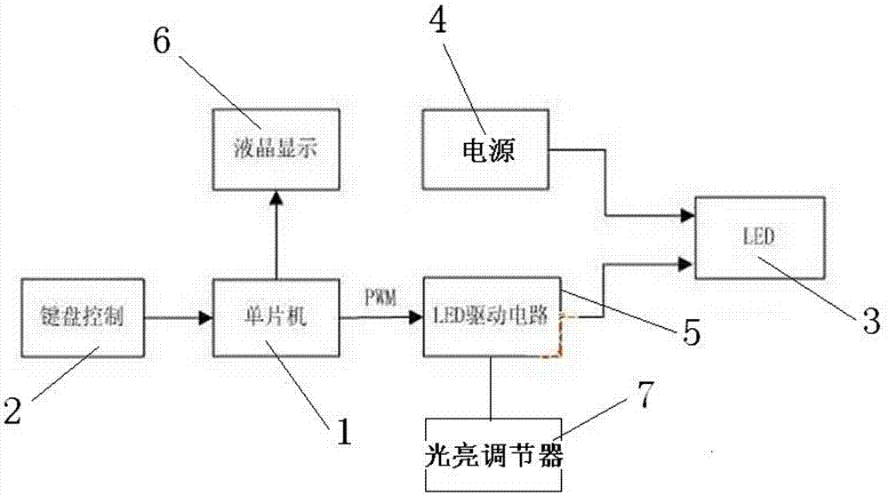
[0016] figure 1 An embodiment of an LED lighting dimming system of the present invention is shown, including a single-chip microcomputer 1, a controller 2, an LED lamp 3, a power supply 4, and an LED driving circuit 5. The controller 2, the single-chip microcomputer 1, and the LED driving circuit 5 and the LED lamp 3 are connected in turn, the single-chip microcomputer 1 is connected with a display 6, and a light regulator 7 is also provided, the light regulator 7 is connected to the LED driving circuit 5, and the power supply 4 is connected to the LED lamp 3, The single-chip microcomputer 1 is connected to the LED driving circuit 5 through PWM (pulse width modulation). The controller 2 is a control keyboard. The display 6 is a liquid crystal display, and an alarm is also installed on the liquid crystal display.


PUM


Abstract

The invention discloses an LED lighting dimming system which comprises a single chip microcomputer, a controller, an LED lamp, a power supply and an LED driving circuit. The controller, the single chip microcomputer, the LED driving circuit and the LED lamp are connected in sequence. The single chip microcomputer is connected with a displayer. The LED lighting dimming system is further provided with a bright adjuster which is connected with the LED driving circuit. The power supply is connected with an LED. The single chip microcomputer is connected with the LED driving circuit in a pulse width modulation (PWM) mode. Any LED chromatography migration cannot happen in dimming due to the fact that the LED always works between full-range current and 0. High dimming accuracy is achieved, and impulse waveforms can be completely controlled to high accuracy, so that the accuracy of 10<-4> can be achieved easily. Even dimming is carried out in a large range, the phenomena of blinking can be avoided. The working condition (the step-up ratio or the step-down ratio) of a constant current source cannot be changed, and problems such as overheating can be avoided.

Description

technical field [0001] The invention relates to the technical field of lighting, in particular to an LED lighting dimming system. Background technique [0002] Ordinary incandescent and halogen lamps usually use thyristors for dimming. Because incandescent lamps and halogen lamps are purely resistive devices, it does not require the input voltage to be a sine wave, because its current waveform is always the same as the voltage waveform, so no matter how the voltage waveform deviates from the sine wave, as long as the effective value of the input voltage is changed, It can be dimmed. [0003] However, the adjustment of the thyristor dimming to the LED light source will produce unexpected problems, that is, the LC filter at the input end will cause the thyristor to oscillate, this oscillation is indifferent to the incandescent lamp, because the thermal inertia of the incandescent lamp makes This oscillation is not visible to the human eye at all, but it produces audible nois...

Claims


Application Information

Patent Timeline
Patent Type & Authority Applications(China)
IPC IPC(8): H05B37/02
Inventor 顾燕萍
Owner SUZHOU CHENGLE ELECTRONICS TECH
Why Eureka
Try Eureka