Tool changing arm of automatic tool replacing mechanism

A technology of automatic tool changing and tool changing arm, applied in the field of tool changing arm, can solve the problems such as difficulty in reducing the total length of the rotating body 2, disadvantageous automatic tool changing mechanism, etc.

Active Publication Date: 2019-07-23
SANJET INT
View PDF6 Cites 2 Cited by
  • Summary
  • Abstract
  • Description
  • Claims
  • Application Information

AI Technical Summary

Problems solved by technology

In order to prevent the abutting member 4 from breaking away from the rotating body 2, a known method is to provide an elongated hole 4a on the abutting member 4, and then pass through the rotating body 2 and the elongated hole 4a with a fixing pin 6, and fix the One end of the pin 6 is inserted into the round hole 2b of the rotating body 2, and the other end is held back by a blocking piece 7 and fixed, so that the abutting member 4 can only move within the long axis of the elongated hole 4a
[0004] It is true that the above-mentioned tool changer arm 1 provides the functions of fast buckling, loosening, and preventing the tool bar 8 from getting loose, but the fixed pin 6 is passed through the body of the rotating body 2 to limit the movement of the abutting member 4. The rotating body 2 of the tool changing arm 1 must have a certain length in order to vacate space to lock the fixing pin 6. In this way, the total length of the rotating body 2 will be difficult to reduce, so this assembly and combination method is not conducive to miniaturized automatic The tool change mechanism adopts

Method used


Image

  • Tool changing arm of automatic tool replacing mechanism
  • Tool changing arm of automatic tool replacing mechanism
  • Tool changing arm of automatic tool replacing mechanism

Examples


Embodiment Construction

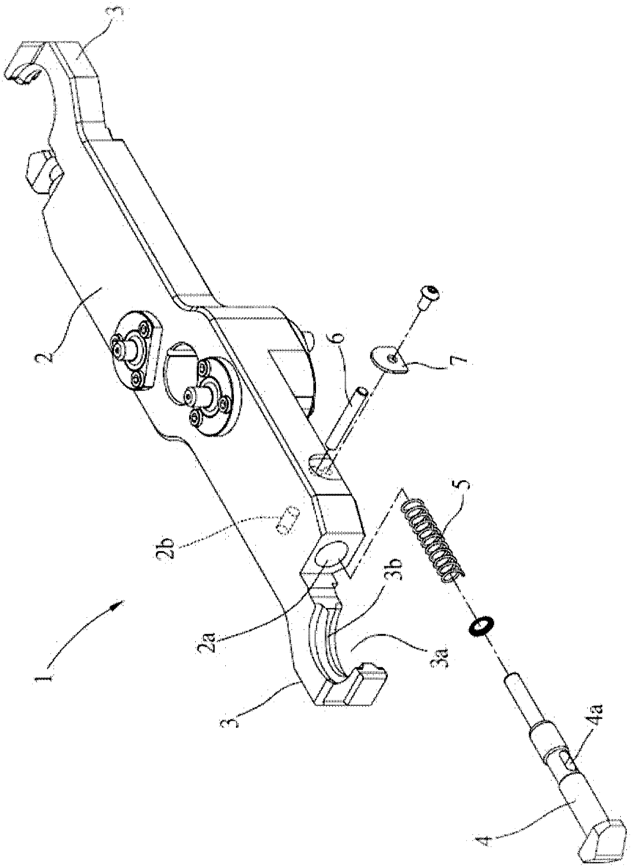
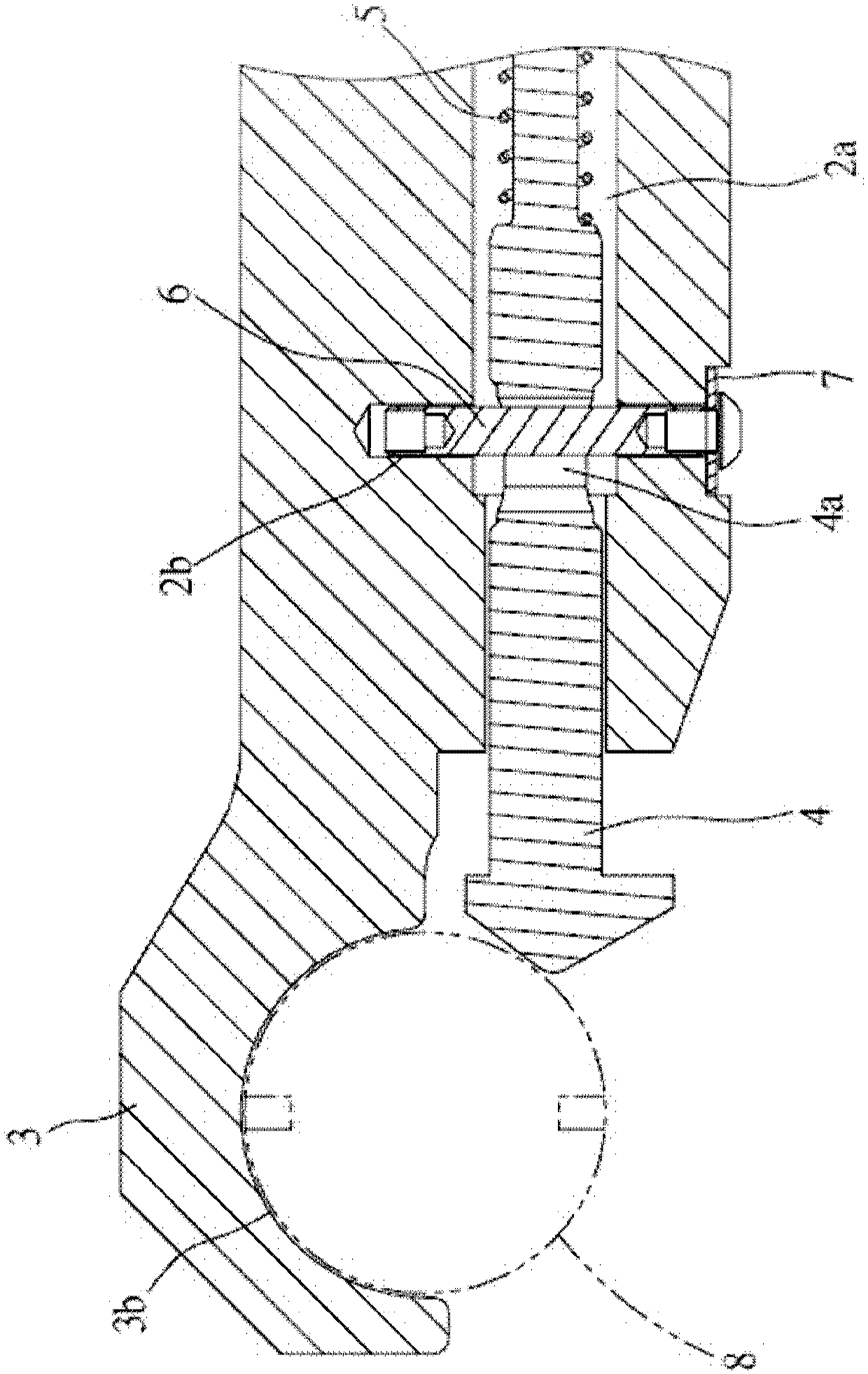
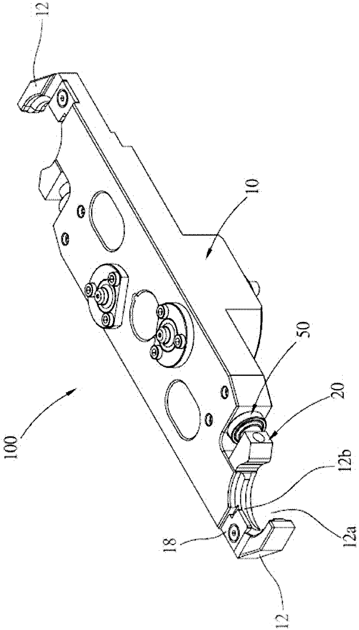
[0031] In order to illustrate the present invention more clearly, a preferred embodiment is given below and described in detail with accompanying drawings. Please refer to Figure 3 to Figure 5 Shown is a tool change arm 100 of an automatic tool change mechanism according to a preferred embodiment of the present invention, which includes a rotating body 10 , two abutting components 20 , two elastic components 30 and two limiting components 40 . The rotating body 10 is connected to the driving device through a rotating shaft (not shown in the figure) and is controlled to rotate. The driving device is a known technology and will not be repeated here. The rotating body 10 takes the connecting shaft as the center of rotation, which refers to the central part of the rotating body 10 in this embodiment.

[0032] The rotating body 10 has a tool buckle part 12 on both sides of the rotation center, which is respectively used to buckle the tool holders of the tool magazine and the mach...


PUM


Abstract

A tool changing arm of an automatic tool replacing mechanism comprises a rotation body, an abutting piece and a limiting piece. A tool buckling part for buckling joint of a tool rod is arranged on oneside of the rotation body. The abutting piece is provided with the limiting piece, and when the limiting piece moves along with the abutting piece and is stopped on a stop part on the rotation body,one abutting-joint end of the abutting piece can make contact with the tool rod located in the tool buckling part. For the situation that a tool replacing arm small in total length needs to be used for a small automatic tool replacing mechanism, the technology can also be used.

Description

technical field [0001] The present invention relates to an automatic tool changing mechanism, in particular to a tool changing arm used for buckling a knife rod to perform a tool changing procedure. Background technique [0002] The tool change arm of the automatic tool change mechanism of the known machine tool is used to quickly exchange the tool holders with the tool in the tool magazine and the machining spindle respectively, so as to improve the work efficiency. Therefore, the tool change arm is used for buckling The structure of the tool holder must have the function of quickly fastening or releasing the tool holder and preventing the tool holder from loosening. [0003] Such as figure 1 and figure 2 As shown, the existing tool changing arm 1 is respectively provided with a buckle part 3 at both ends of its rotating body 2. The knife part 3 has a side opening 3a for the knife rod 8 to enter and exit, and has a concave The fastening inner edge 3b cooperates with the...

Claims


Application Information

Patent Timeline
IPC IPC(8): B23Q3/155
CPCB23Q3/1554
Inventor 张庆三
Owner SANJET INT
Why Eureka
Try Eureka