
Connector

A technology for connectors and connector assemblies, applied in the direction of connections, parts of connecting devices, coupling devices, etc., can solve the problems of not being universal and reducing the integrity of electrical signals.

Inactive Publication Date: 2019-07-30
3M INNOVATIVE PROPERTIES CO
View PDF6 Cites 0 Cited by
  • Summary
  • Abstract
  • Description
  • Claims
  • Application Information

AI Technical Summary

Problems solved by technology

However, such packages are not universal to mate with different receptacle connectors or receptacles
[0004] Additionally, as electrical signal transmission speeds increase, electromagnetic interference (EMI) needs to be controlled or minimized so as not to degrade electrical signal integrity

Method used


Image

  • Connector
  • Connector
  • Connector

Examples


Embodiment Construction

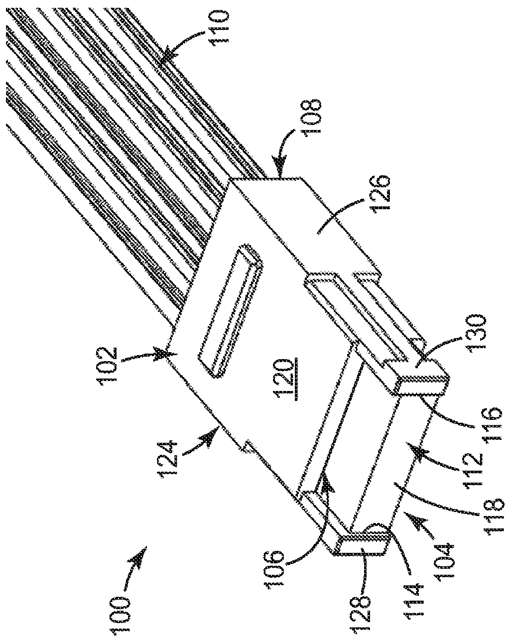
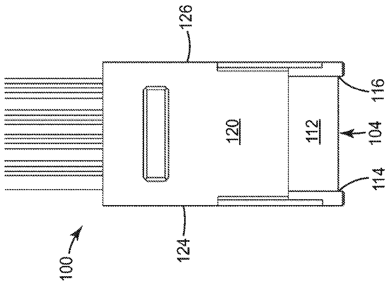
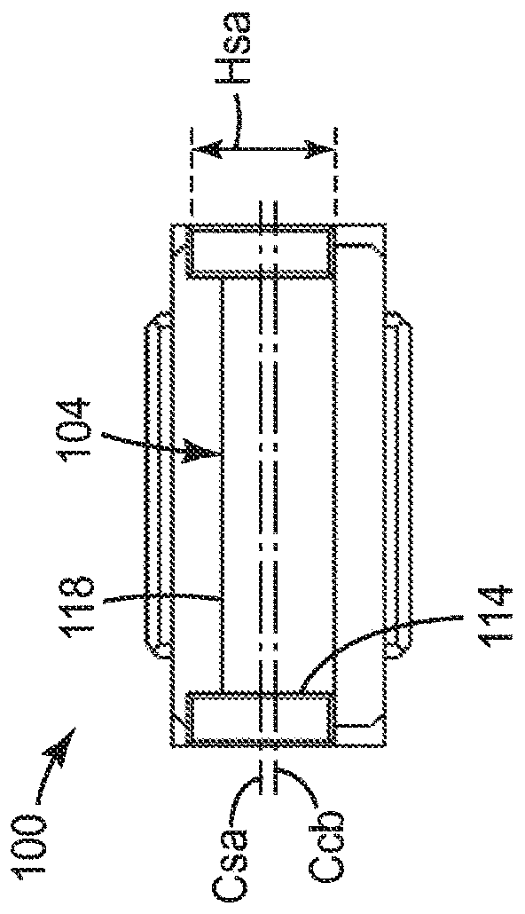
[0064] figure 1 is a connector in the form of a plug connector 100 according to a first embodiment of the invention, and figure 2 , image 3 and Figure 4 respectively figure 1 Top, front and side views of the plug connector. The plug connector 100 includes an insulating housing 102 and a circuit board 104 disposed in the insulating housing 102 . In this embodiment, the insulative housing 102 is molded with the circuit board 104 , and the insulative housing 102 includes a front opening 106 and a rear opening 108 for receiving a plurality of electrical wires 110 .

[0065] The circuit board 104 includes a mating section 112 for mating with a corresponding mating section of a mating connector (not shown). Such as figure 1 As shown, the mating section 112 is arranged to protrude outwardly from the front opening 106 . The mating section 112 of the circuit board 104 includes opposing side edges 114 , 116 and terminates in a front edge 118 disposed between the opposing side ...


PUM


Abstract

In a specific embodiment, a connector 100 is disclosed. The connector 100 comprises an insulative housing 102 defining a rear opening 108 for receiving a plurality of electrical wires 110 and a frontopening 106 and a circuit board 104 disposed in the housing 102 and comprising a mating section 112 for mating with a corresponding mating section of a mating connector. The mating section 112 protrudes outwardly from the front opening 106 and terminates at a front edge 118 disposed between opposing side edges 114,116 of the mating section112. The connector 100 further comprises opposing side arms128,130 extending forwardly from opposing lateral sides 124,126 of the front opening 106 along, adjacent and beyond corresponding side edges 114,116 of the mating section 112 with a maximum separation between each side edge 114,116 and the corresponding side arm 128,130 being sufficiently small so that when the connector 100 mates with a mating connector, no portion of the mating connector can beinserted between the side edge 114,116 and the corresponding side arm 128,130. Other exemplary embodiments are also disclosed.

Description

technical field [0001] This application relates to connectors. More particularly, in at least one aspect, the present application relates to electrical connectors for connecting electrical cables to printed circuit boards. Background technique [0002] Cable connector assemblies are commonly used to connect cables to printed circuit boards (PCBs). A typical cable connector assembly may include a plug connector and a receptacle connector arranged to mate with the plug connector. The cable terminates in a printed circuit card of the plug connector, and the printed circuit card includes electrical contacts for connection to electrical terminals of the receptacle connector mounted to the PCB. [0003] The printed circuit card is usually encapsulated to form the plug / header and the encapsulation provides protection by means of the cable to prevent any damage to the printed circuit card and the soldering / termination area. The package may also have additional guiding and polariz...

Claims


Application Information

Patent Timeline
Patent Type & Authority Applications(China)
IPC IPC(8): H01R12/72H01R13/453H01R13/6583H01R13/6594
CPCH01R12/725H01R13/4538H01R13/6583H01R13/6594H01R12/727H01R12/724
Inventor K·H·李S·班德胡乔云龙R·L·维塔帕里林进和
Owner 3M INNOVATIVE PROPERTIES CO
Features
  • Generate Ideas
  • Intellectual Property
  • Life Sciences
  • Materials
  • Tech Scout
  • Unparalleled Data Quality
  • Higher Quality Content
  • 60% Fewer Hallucinations
Learn More