
Hydraulic lash adjuster assembly sleeves

A technology of gap adjuster and casing, which is applied in the direction of engine components, machines/engines, mechanical equipment, etc.

Pending Publication Date: 2019-07-30
EATON INTELLIGENT POWER LIMITED
View PDF6 Cites 0 Cited by
  • Summary
  • Abstract
  • Description
  • Claims
  • Application Information

AI Technical Summary

Problems solved by technology

However, the size of the lifter bore of the HLA mechanism may vary between different types of engines, so a specially sized HLA mechanism is required for each size of lifter bore

Method used


Image

  • Hydraulic lash adjuster assembly sleeves
  • Hydraulic lash adjuster assembly sleeves
  • Hydraulic lash adjuster assembly sleeves

Examples


Embodiment Construction

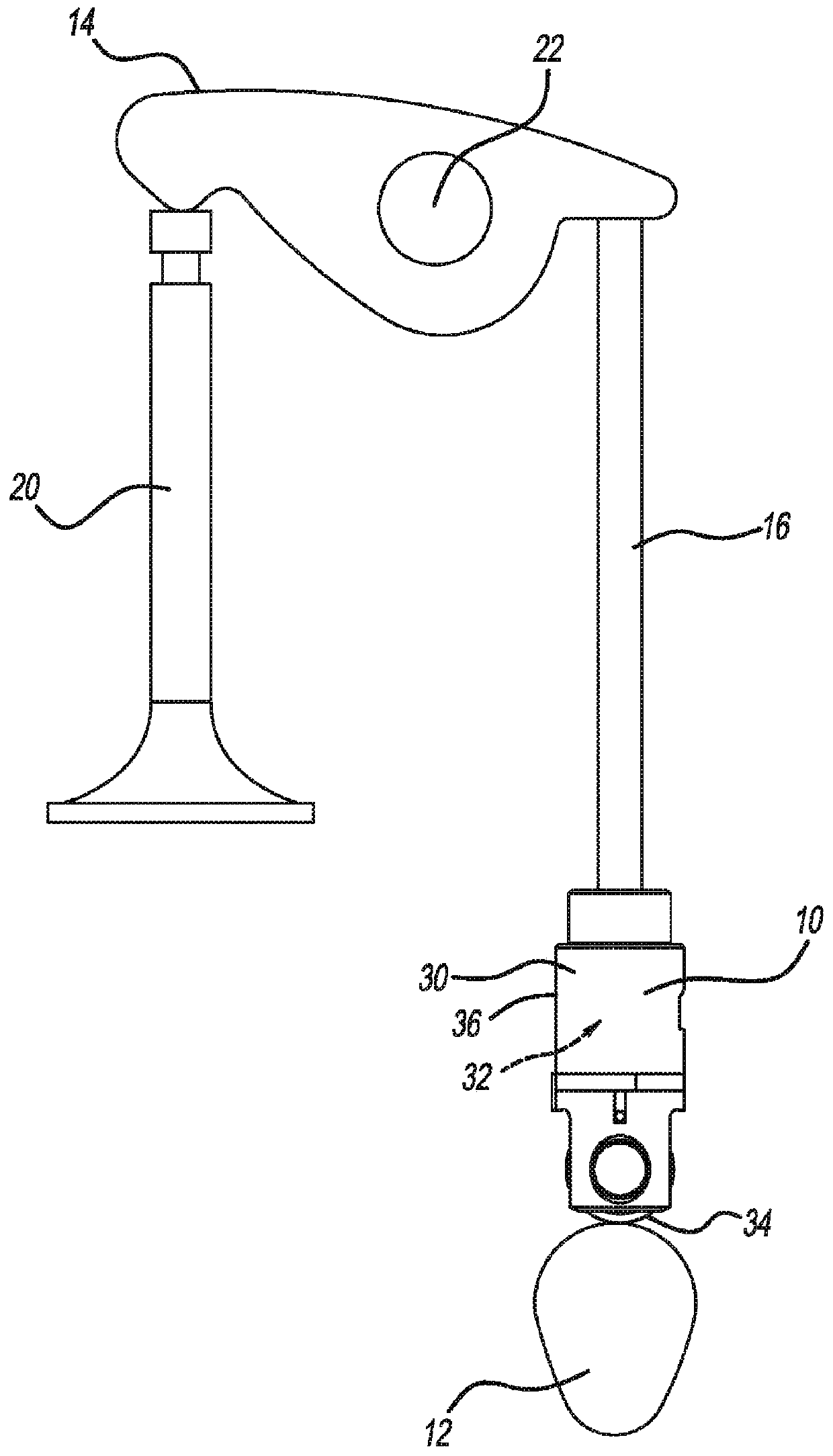
[0024] first reference figure 1 , shows a hydraulic lash adjuster (HLA) roll lifter constructed in accordance with one example of the present disclosure and is generally identified with reference numeral 10 . The roll lifter 10 is shown as part of a V-train arrangement. It should be understood, however, that although shown in a V-shaped arrangement, it is within the scope of the present disclosure that the various features described herein be used in other arrangements. In this regard, the features described herein associated with the valve train arrangement 10 may be suitable for a variety of applications. The cam lobe 12 indirectly drives the first end of the rocker arm 14 with a push rod 16 . It should be understood that in some configurations, such as an overhead cam, the roller lifter may be a direct connection between the cam lobe 12 and the rocker arm 14 . The second end of the rocker arm 14 actuates the valve 20 . As the cam lobe 12 rotates, the rocker arm 14 pivot...


PUM


Abstract

A hydraulic lash adjuster (HLA) sleeve configured to be received within a lifter bore of an engine block, includes a cylindrical sleeve having an outer surface defining an outer diameter, and an innersurface defining an inner diameter. The outer diameter is sized for an interference fit with the lifter bore to prevent rotation of the HLA sleeve within the lifter bore. The inner diameter is sizedto receive a lifter.

Description

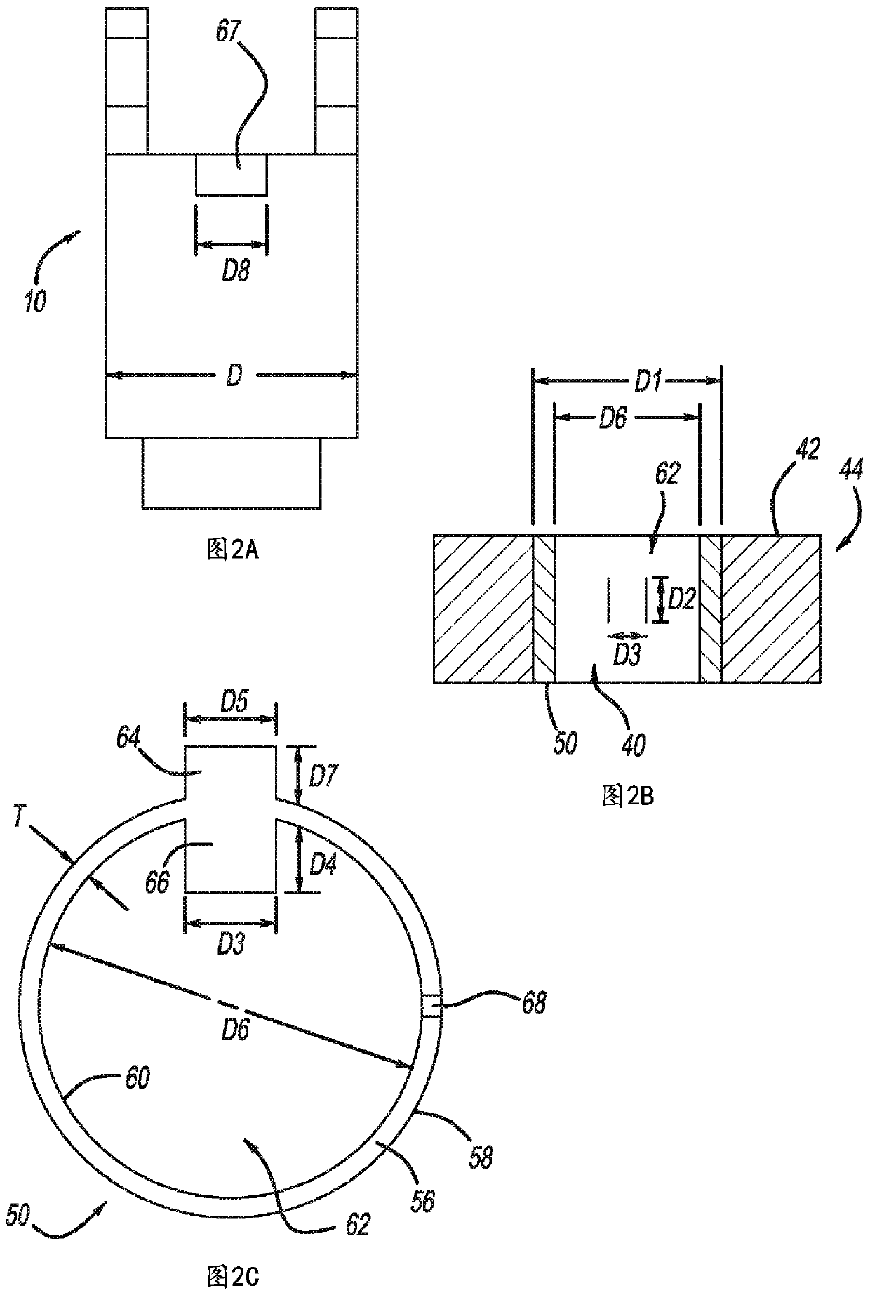
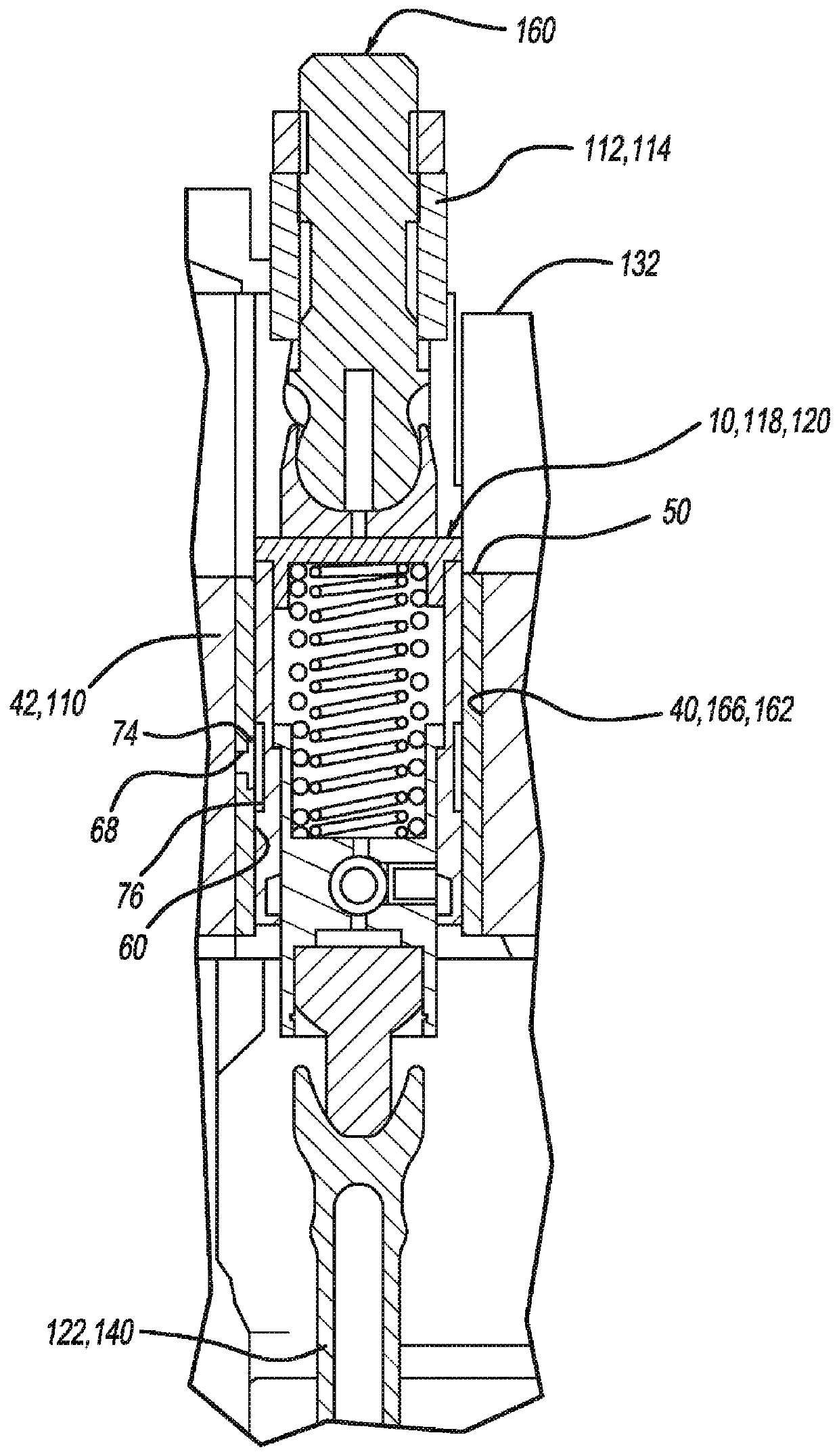
[0001] Cross References to Related Applications [0002] This application claims the benefit of U.S. Provisional Application No. 62 / 409,084, filed October 17, 2016, the contents of which are incorporated herein by reference. technical field [0003] The present disclosure relates to a hydraulic lash adjuster assembly, and more particularly, to a set of bushings that enable the hydraulic lash adjuster assembly to be used in multiple engine applications. Background technique [0004] Some internal combustion engines may utilize rocker arms to transfer the rotational motion of a cam into linear motion suitable for opening and closing engine valves. Deactivating the rocker arms can incorporate a hydraulic lash adjuster (HLA) mechanism into the lifter bore of the engine block to allow selective activation and deactivation of the rocker arms. However, the size of the lifter bore of the HLA mechanism may vary between different types of engines, thus requiring a specially sized HLA...

Claims


Application Information

Patent Timeline
IPC IPC(8): F01L1/24F01L1/14
CPCF01L1/146F01L2001/2427F01L2820/01F01L1/24F01L2001/256F01L2307/00F01L2305/00
Inventor 利昂·布朗小詹姆斯·E·麦卡锡
Owner EATON INTELLIGENT POWER LIMITED
Learn More