
Display device

A display device and display area technology, which is applied in the direction of identification devices, static indicators, instruments, etc., can solve the problems that it is difficult to achieve high screen-to-body ratio, and the notch area cannot display images, etc., and achieve the effect of high screen-to-body ratio

Active Publication Date: 2019-08-02
AU OPTRONICS CORP
View PDF5 Cites 4 Cited by
  • Summary
  • Abstract
  • Description
  • Claims
  • Application Information

AI Technical Summary

Problems solved by technology

[0003] However, since the notch area occupies part of the screen area, and the notch area cannot display images, the overall image display area has a gap, making it difficult to achieve a high screen ratio design.

Method used


Image

  • Display device
  • Display device
  • Display device

Examples


Embodiment Construction

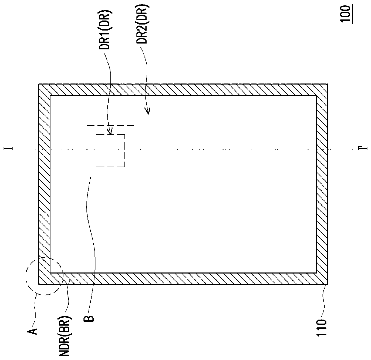
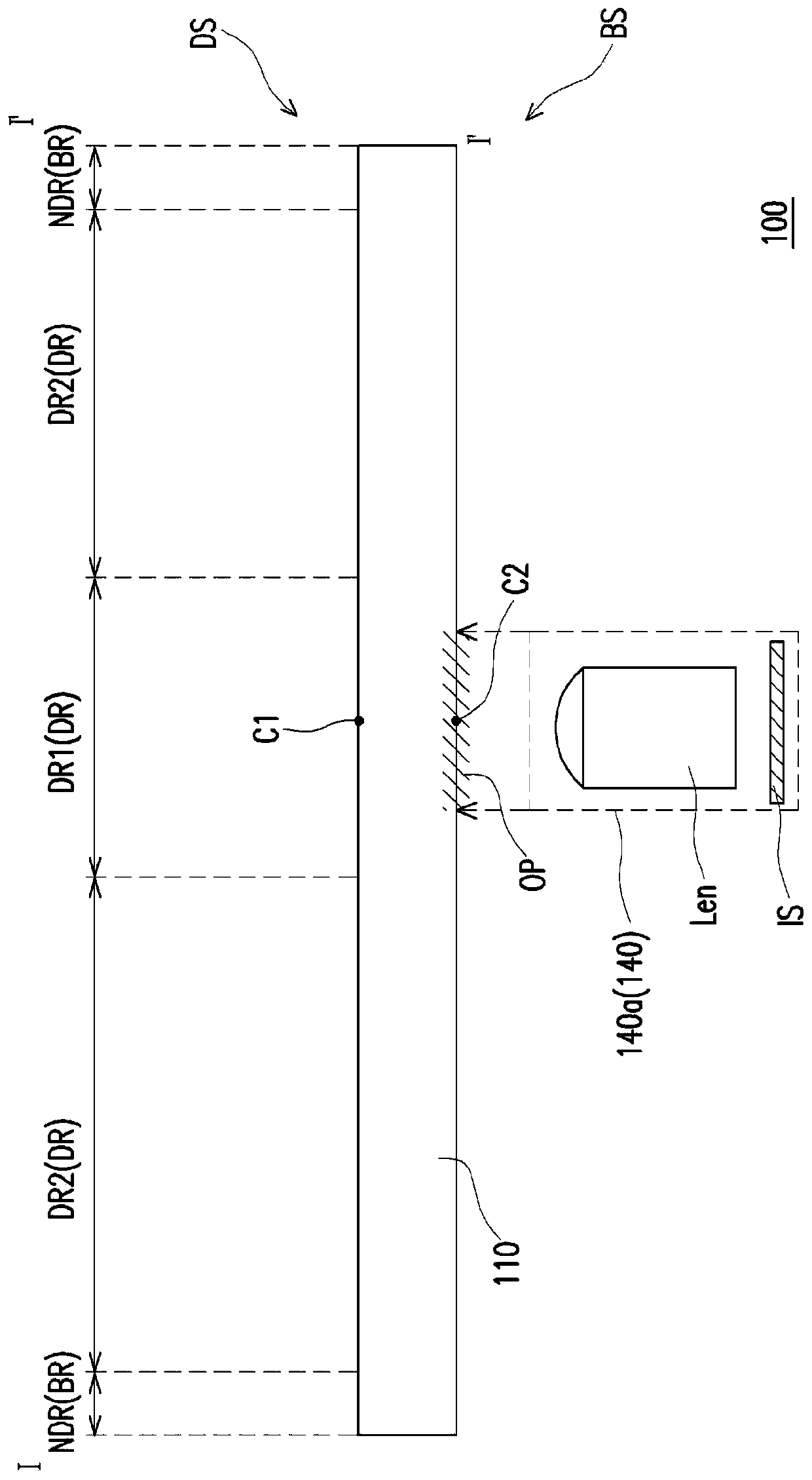
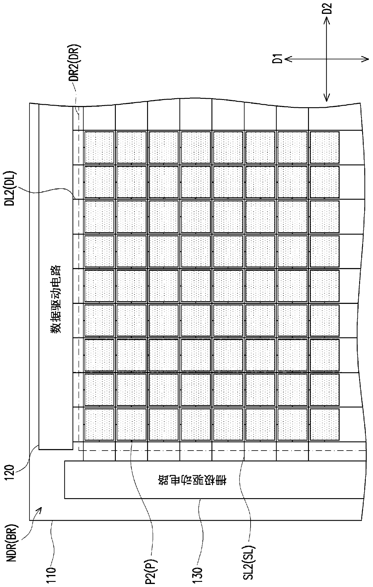
[0065] Figure 1A It is a schematic top view of a display device according to an embodiment of the present invention. Figure 1B for Figure 1A Schematic cross-sectional view of the middle section line I-I'. Figure 1C for in Figure 1A An enlarged schematic view of region A in . Figure 1D for in Figure 1A An enlarged schematic view of region B in . Figure 1E for Figure 1D A schematic top view of the first pixel and the second pixel in . Figure 1F for Figure 1D The cross-sectional view of the first pixel and the second pixel in . It should be noted that at Figure 1D , specifically shows the top-view structure of the first pixel and the second pixel. In other drawings, the first pixel and the second pixel are marked in different ways.

[0066] Firstly, the corresponding functions of different regions in the display device 100 will be introduced.

[0067] Please refer to Figure 1A Generally speaking, in this embodiment, the display device 100 has a display region...


PUM


Abstract

A display device has a display area. The display area comprises a first area and a second area. The display device comprises a substrate, a plurality of data lines and a plurality of scanning lines. The substrate includes a plurality of first pixels and a plurality of second pixels. The first pixels are arranged in the first area and are annularly arranged. The second pixels are disposed in the second area. In addition, the display device is also provided.

Description

technical field [0001] The invention relates to a display device. Background technique [0002] In a general mobile phone, a notch (Notch Region) is provided on the top of the screen of the mobile phone to set a camera element or other components with different functions, so that the mobile phone can realize different functions. [0003] However, since the notch area occupies part of the screen area, and the notch area cannot display images, the overall image display area has a gap, making it difficult to achieve a high screen ratio design. Contents of the invention [0004] The invention provides a display device which has the advantages of high screen-to-body ratio and multifunctional applications. [0005] An embodiment of the invention provides a display device. The display area of ​​the display device includes a first area and a second area. The display device includes a substrate, a plurality of data lines and a plurality of scan lines. The data lines include a p...

Claims


Application Information

Patent Timeline
IPC IPC(8): H01L27/32G09F9/302G09G3/3225
CPCG09F9/302G09G3/3225H10K59/131
Inventor 陈鹏聿郭雅佩陈弘祥
Owner AU OPTRONICS CORP
Learn More