
Automatic adjusting system and method of laser resonant cavity reflector

An automatic adjustment and reflector technology, which is applied in the field of lasers, can solve problems affecting the use efficiency of lasers, affect laser output power and beam quality, etc., and achieve the effect of improving use efficiency and increasing adjustment speed

Inactive Publication Date: 2019-08-09
CHANGCHUN INST OF OPTICS FINE MECHANICS & PHYSICS CHINESE ACAD OF SCI
View PDF8 Cites 9 Cited by
  • Summary
  • Abstract
  • Description
  • Claims
  • Application Information

AI Technical Summary

Problems solved by technology

However, as the laser usage time increases, the laser resonator mirror will undergo slight deflection and other movements, which will affect the laser output power and beam quality. If you want to restore the predetermined laser output, you need to stop the laser, disassemble the laser and readjust the resonator, which will seriously affect Laser usage efficiency

Method used


Image

  • Automatic adjusting system and method of laser resonant cavity reflector

Examples


Embodiment Construction

[0022] In order to make the object, technical solution and advantages of the present invention clearer, the present invention will be further described in detail below in conjunction with the accompanying drawings and specific embodiments. It should be understood that the specific embodiments described here are only used to explain the present invention, not to limit the present invention.

[0023] In order to make the description of the present disclosure more detailed and complete, the following provides an illustrative description of the implementation modes and specific examples of the present invention; but this is not the only form for implementing or using the specific embodiments of the present invention. The description covers features of various embodiments as well as method steps and their sequences for constructing and operating those embodiments. However, other embodiments can also be used to achieve the same or equivalent functions and step sequences.

[0024] T...


PUM


Abstract

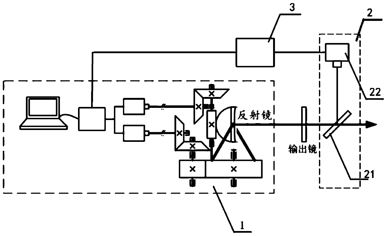
The invention provides an automatic adjusting system of a laser resonant cavity reflector. The system comprises a remote angle adjusting device, a light beam monitoring device and a data processing module. The light beam monitoring device is configured to detect the centroid data of a laser output by a laser in real time, compare the centroid data with initial centroid data to determine whether the centroid data exceeds a centroid fluctuation range or not, and convert the centroid fluctuation quantity and the fluctuation direction into driving signals and send the driving signals to the remoteangle adjusting device if yes. The present invention further provides an automatic adjusting method of a laser resonant cavity reflector. The method can monitor the parameters of the laser output bythe laser in use in real time to determine whether a laser resonant cavity reflector is moved or not, can determine the movement data of the laser resonant cavity reflector according to the parameterchange trend and can feedback the movement data to the automatic adjusting system of the laser resonant cavity reflector to achieve rapid and automatic adjusting of the laser resonant cavity reflectorso as to improve the adjustment rate of the reflector and improve the use efficiency of the laser.

Description

technical field [0001] The invention relates to the technical field of lasers, in particular to an automatic adjustment system and method for a reflector of a laser resonator cavity. Background technique [0002] The position and angle of the mirror in the laser resonator affect the power and beam quality of the output laser. The precise adjustment of the laser resonator mirror has always been an important link in the debugging of the laser resonator. A typical laser resonator consists of a planar output mirror and a reflective mirror with curvature to form a plano-concave resonator. By adjusting the position and angle of the two mirrors, a predetermined laser output can be obtained. In this state, the output mirror and reflector The mirror is fastened to obtain a laser resonator that meets the design requirements. However, as the laser usage time increases, the laser resonator mirror will undergo slight deflection and other movements, which will affect the laser output po...

Claims


Application Information

Patent Timeline
Patent Type & Authority Applications(China)
IPC IPC(8): H01S3/105
CPCH01S3/105
Inventor 张阔陈飞潘其坤郭劲于德洋孙俊杰何洋
Owner CHANGCHUN INST OF OPTICS FINE MECHANICS & PHYSICS CHINESE ACAD OF SCI
Learn More