A self-cleaning dust collector

A dust collector and dust filtering technology, which is applied in chemical instruments and methods, separation methods, dispersed particle separation, etc., can solve the problems of poor dust removal effect and frequent cleaning of dust collectors, so as to improve the scope of application, improve thrust, and improve cleaning efficiency. Effect

Active Publication Date: 2021-06-25
苏州市拓镨洁净技术有限公司
View PDF0 Cites 0 Cited by
  • Summary
  • Abstract
  • Description
  • Claims
  • Application Information

AI Technical Summary

Problems solved by technology

[0004] The purpose of the present invention is to provide a self-cleaning dust collector with good cleaning effect and no need for frequent cleaning to solve the problem that the dust removal effect of the dust collector is poor and frequent cleaning is required

Method used


Image

  • A self-cleaning dust collector
  • A self-cleaning dust collector
  • A self-cleaning dust collector

Examples


Embodiment 1

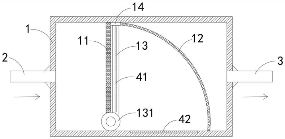
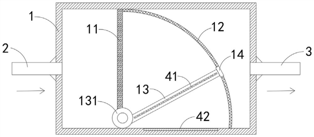
[0032] Such as Figure 1-3 As shown, a self-cleaning dust collector includes a housing 1, an air intake pipe 2 and an exhaust pipe 3, and the air intake pipe 2 and the exhaust pipe 3 are respectively fixedly installed at both ends of the housing 1, and the housing 1 is provided with:

[0033] The first dust filter plate 11, the first dust filter plate 11 is fixedly connected on the inner side wall of the housing 1, the first dust filter plate 11 is vertically arranged, and the two ends of the first dust filter plate 11 are respectively connected to the two side walls of the housing 1 Fixed and sealed connection, the first dust filter plate 11 separates the housing 1 into a settling area and a filtering area, the side of the first dust filter plate 11 close to the intake pipe 2 is a settling area, which is used to collect large particles of settled smoke particles, the first dust filter plate 11 The side close to the exhaust pipe 3 is a filtering area, which is used for seconda...

Embodiment 2

[0043] Such as Figure 4-5As shown, the difference between this embodiment and Embodiment 1 is that a liquid storage box 51 is provided on the side of the first dust filter plate 11 close to the intake pipe 2, the liquid storage box 51 is filled with cleaning agent, and the liquid storage box 51 is fixedly connected On the inner side wall of the housing 1, a windshield 52 is rotatably connected to the inner sidewall of the housing 1, and a liquid spray pipe 521 is installed through the windshield 52, and the windshield 52 and the liquid storage box 51 are fixedly connected. There is an elastic liquid storage bag 53, and the liquid storage box 51 and the liquid spray pipe 521 are all connected with the elastic liquid storage bag 53. The direction of drainage is as Figure 5 Shown by the arrow in) is connected with the elastic liquid storage bag 53, and the liquid spray pipe 521 is a one-way liquid spray pipe (the liquid discharge direction of the one-way liquid spray pipe is a...


PUM


Abstract

The invention belongs to the field of dust collectors, and in particular relates to a self-cleaning dust collector, which includes a casing, an air inlet pipe and an exhaust pipe, and the air inlet pipe and the exhaust pipe are fixedly installed at both ends of the casing respectively, and the casing is provided with: the first One dust filter plate, the first dust filter plate is fixedly connected to the inner wall of the shell, the first dust filter plate separates the shell into a settling area and a filter area; the second dust filter plate, the second dust filter plate is a curved plate, and the second dust filter plate One end of the plate is fixedly connected with the first dust filter plate, and the other end of the second dust filter plate is fixedly connected with the inner wall of the housing. The second dust filter plate divides the filter area into a secondary filter area and a discharge area; rotating the sealing plate, rotating the sealing One end of the plate is fixedly connected with a rotating column, and the rotating column is rotatably connected in the housing; the cleaning strip is fixedly connected to the end surface of the rotating sealing plate away from the rotating column. The invention can automatically adjust the dust filtering area according to the air intake volume, has a wide application range, and can achieve the effect of self-cleaning, and can reduce the cleaning frequency of the dust collector.

Description

technical field [0001] The invention belongs to the field of dust collectors, in particular to a self-cleaning dust collector. Background technique [0002] The function of the dust collector is to separate the dust from the flue gas to avoid air pollution caused by the direct discharge of the flue gas. Since the dust is mostly fine particles, the existing dust collector can generally complete the dust filtration through the dust filter plate, but in practice During use, the dust filter holes on the dust filter plate are easily blocked, resulting in poor dust removal effect of the dust collector. The staff need to frequently disassemble and clean the dust filter plate to ensure the dust removal effect of the dust collector and bring new benefits to daily use. A lot of inconvenience. [0003] For this reason, we propose a self-cleaning dust collector to solve the above problems. Contents of the invention [0004] The purpose of the present invention is to provide a self-c...

Claims


Application Information

Patent Timeline
Patent Type & Authority Patents(China)
IPC IPC(8): B01D50/00
CPCB01D50/60
Inventor 程菲
Owner 苏州市拓镨洁净技术有限公司
Why Eureka
Try Eureka