Angiography machine

An imaging machine and blood vessel technology, which is used in medical science, radiation safety devices, instruments used for radiological diagnosis, etc., can solve the influence of human factors of adjustment accuracy, and does not display the angle information of the C-arm and the C-arm frame, It is not good for doctors to check and other problems to achieve the effect of improving accuracy

Inactive Publication Date: 2019-08-16
SHANGHAI UNITED IMAGING HEALTHCARE
View PDF7 Cites 5 Cited by
  • Summary
  • Abstract
  • Description
  • Claims
  • Application Information

AI Technical Summary

Problems solved by technology

[0003] The monitors of the existing medical systems containing angiography machines are all installed opposite the operating bed. When the doctor moves the C-arm, he needs to repeatedly observe the movement of the monitor and the C-arm frame, which is not conducive to the doctor’s viewing, and

Method used


Image

  • Angiography machine
  • Angiography machine

Examples


Embodiment 1

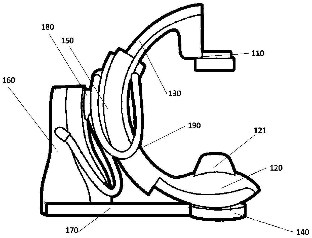
[0027] figure 1 A schematic structural diagram of an angiography machine provided in Embodiment 1 of the present invention, as shown in figure 1 As shown, the embodiment of the present invention provides an angiography machine, including: a detector 110, a radiation source 120, a collimator 121, a C-arm 130, a rotating column 140, a C-arm sliding rail 150, a support arm 160, The base 170 , the connection part 180 and the display 190 . Wherein, the C-arm 130 is placed in the C-arm slide rail 150 and can move in the C-arm slide rail 150; the detector 110 is arranged at one end of the C-arm 130; the ray source 120 is arranged in the C-arm slide rail 150; The other end of 130 is set opposite to the detector 110; one end of the base 170 is connected to the support arm 160; the display 190 is used to display the angle information of the C-arm 130, the height information of the bed surface, the collision information and the radiation source 120 and the detector. At least one of the...

Embodiment 2

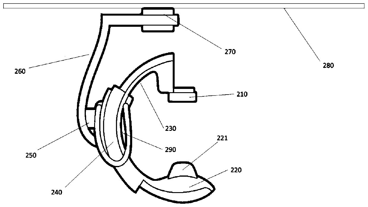
[0039] figure 2 A schematic structural diagram of an angiography machine in Embodiment 2 of the present invention, as shown in figure 2 As shown, the difference between this embodiment and the first embodiment is that the base 180 is not included, but a track 290 is provided, so that the angiography machine can be suspended and fixed. An embodiment of the present invention provides an angiography machine, including: a detector 210, a radiation source 220, a collimator 221 arranged close to the radiation source 220, a C-arm 230, a C-arm sliding rail 240, a connecting part 250, a support Arm 260 , rotating column 270 , track 280 , display 290 . Wherein, the display 290 is used to display at least one of the angle information of the C-arm 130 , the height information of the bed surface, the collision information, and the distance SID between the radiation source 120 and the imaging plane of the detector 110 .

[0040] Optionally, the support part 260 may be a boom.

[0041] ...


PUM


Abstract

The invention discloses an angiography machine, which comprises an X-ray source, a detector, a C-shaped arm, a C-shaped arm slide rail, a supporting arm, a connection portion and a display. The C-shaped arm is arranged in the C-shaped arm slide rail and capable of sliding in the C-shaped arm slide rail; the detector is arranged at one end of the C-shaped arm; the X-ray source is arranged at the other end of the C-shaped arm and opposite to the detector; the display is used for displaying at least one of angle information of the C-shaped arm, bed height information, collision information and distance SID between the X-ray source and an imaging surface of the detector. By additional arrangement of the display on the side of the C-shaped arm, display contents of the display can be conveniently checked by an operator or doctor, and accuracy in movement of the C-shaped arm and safety in a detection process are improved.

Description

technical field [0001] Embodiments of the present invention relate to the technical field of medical equipment, in particular to an angiography machine. Background technique [0002] At present, the large C-arm, also known as the large C, DSA angiography machine, is a major breakthrough in X-ray diagnostic technology, and is widely used in the diagnosis and treatment of vascular diseases. [0003] The monitors of the existing medical systems containing angiography machines are all installed opposite the operating bed. When the doctor moves the C-arm, he needs to repeatedly observe the movement of the monitor and the C-arm frame, which is not conducive to the doctor’s viewing, and often requires It takes a long time to adjust the angle of the C-arm, and the adjustment accuracy is seriously affected by human factors. At present, the existing angiography machine does not have a device capable of displaying the angle information of the C-arm and the C-arm frame on the side of t...

Claims


Application Information

Patent Timeline
IPC IPC(8): A61B6/00A61B6/10
CPCA61B6/107A61B6/4441A61B6/481A61B6/547
Inventor 孙彪
Owner SHANGHAI UNITED IMAGING HEALTHCARE
Why Eureka
Try Eureka