Intracranial cerebrospinal fluid drainage tube

A drainage tube and cerebrospinal fluid technology, applied in wound drainage devices, catheters, balloon catheters, etc., can solve the problems of increasing the nursing cost of doctors, poor drainage, easy displacement, etc., to maintain stability, increase the number of drainage holes, The effect of increasing the contact area

Pending Publication Date: 2019-08-16
深圳市慧极创新医疗科技有限公司
View PDF8 Cites 4 Cited by
  • Summary
  • Abstract
  • Description
  • Claims
  • Application Information

AI Technical Summary

Problems solved by technology

After the drainage tube is placed, it is easy to shift or even fall out during the contin

Method used


Image

  • Intracranial cerebrospinal fluid drainage tube
  • Intracranial cerebrospinal fluid drainage tube
  • Intracranial cerebrospinal fluid drainage tube

Examples


Embodiment 2

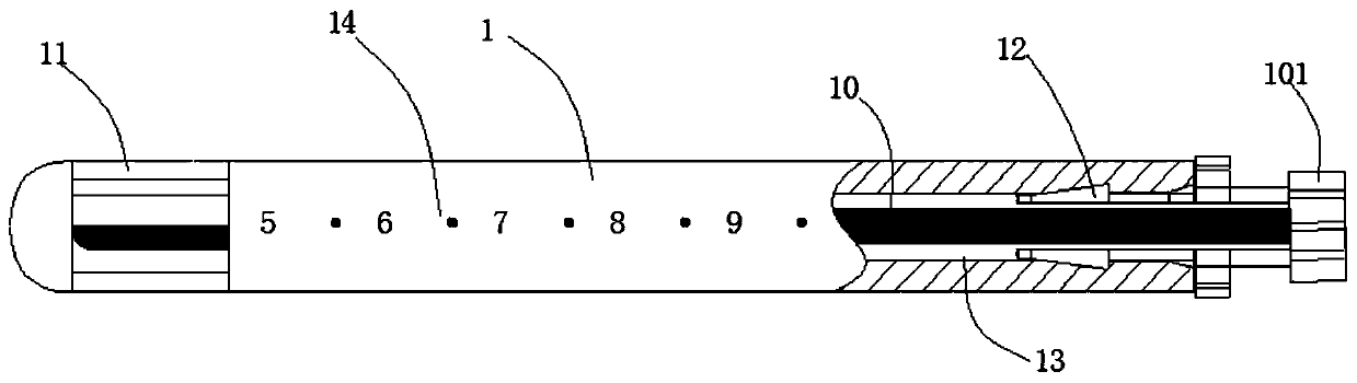
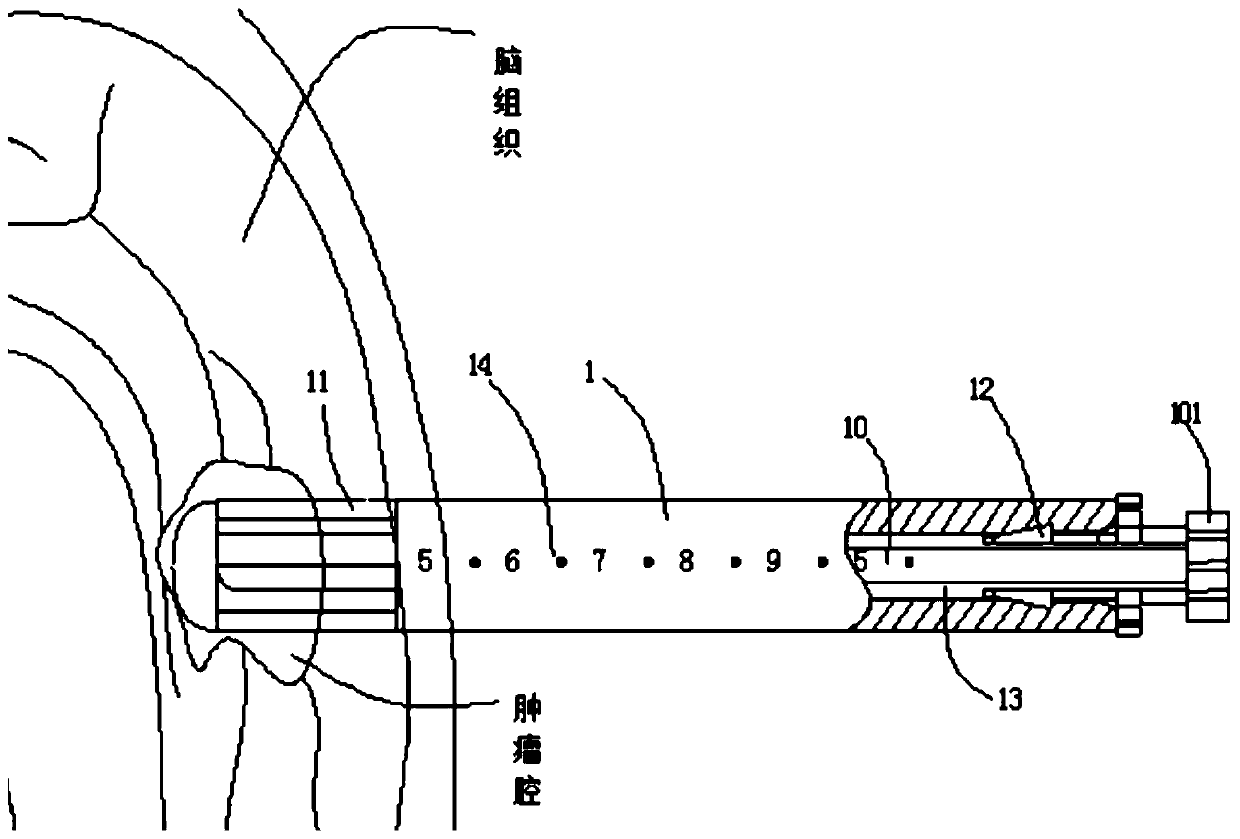
[0044] Figure 5 The middle and outer expansion structure 11 is composed of a porous balloon 112 and a supporting keel 111. The porous balloon 112 is made of soft elastic polymer materials, such as but not limited to silica gel, latex and other materials. The surface of the porous balloon 112 has several drainage holes 113 to support Keel 111 is made of elastic metal material, such as but not limited to nickel-titanium wire, stainless steel wire and other materials, pre-molded into Figure 5 The shape of the middle and outer expansion structure 11;

[0045] The use process of the drainage tube 1 in this embodiment is basically the same as the above-mentioned scheme. After the assembly of the guide needle 10 and the drainage tube 1 is completed, the drainage tube 1 is stretched, and the outward expansion structure 11 is folded. The expansion structure 11 expands outward under the elastic force of the supporting keel 111, supports the porous balloon 112 on the surface, and the ...

Embodiment 3

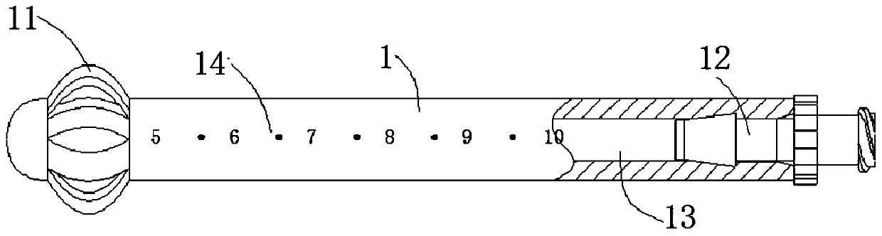
[0048] Some ventricular tumors are accompanied by intracranial infection or purulent cerebrospinal fluid, and conventional drainage is difficult to control intracranial infection. Image 6 Middle drainage tube 1.

[0049] The drainage tube 1 is a single-tube multi-chamber structure, and is provided with a drainage chamber 13 and several drug injection chambers 15 (flush chambers). , and on the outer side of the expansion structure 11, there is a medicine injection hole 114, the medicine injection hole 114 is connected with the injection cavity 15 and corresponds one by one, the gap between the drainage cavity 13 and the expansion structure 11 is connected, the drainage cavity 13 and the injection cavity 15 The two are separated at the connecting seat 16, and are respectively connected to the drainage branch 17 and the injection branch 18, and the drainage branch 17 is connected to the in vitro sterile drainage bag through the Luer connector 12.

[0050] In this embodiment, th...


PUM


Abstract

The invention discloses an intracranial cerebrospinal fluid drainage tube in the technical field of medical devices. An inner cavity of the drainage tube is transversely provided with a guide needle.The right side of the guide needle runs through a Luer taper and extends outside the right side of the drainage tube, the left side of the guide needle is connected with the left side of the drainagecavity, and the right side of the guide needle is provided with a Luer block shot; the front end face of the drainage tube is provided with a scale line from left to right in turn, and the left side of the drainage tube is provided with external expansion structures in an annular manner. The drainage tube has the advantages that through the external expansion structures, the drainage tube can expand outward to fill a tumor cavity in the early stage of tumor removal and plays a role in temporarily supporting and occupying a space, and the drainage tube can be fixed to prevent displacement and dislocation. With the process of continuous drainage and reset of a brain tissue, the brain tissue is contracted by squeezing the external expansion structures, and the elastic external expansion structures are contracted and gathered; at the same time, gaps between the external expansion structures persistently exist. The drainage tube maintains the drainage function continuously and the stabilityof the intracranial pressure is maintained.

Description

technical field [0001] The invention relates to the technical field of medical devices, in particular to an intracranial cerebrospinal fluid drainage tube. Background technique [0002] Ventricular drainage is performed by drilling through the skull for lateral ventricle puncture, or during craniotomy, the front end of the drainage tube with several side holes is placed in the ventricle, and the other end is connected to a sterile drainage bag to drain the cerebrospinal fluid out of the body. It is a commonly used technical method in neurosurgery and a common treatment measure after craniocerebral surgery. The purpose is to discharge intraventricular hemorrhage, reduce wound cerebrospinal fluid leakage, reduce intracranial pressure, and prevent cerebral herniation; [0003] The most commonly used clinically is a single-tube single-lumen drainage tube with multiple side holes for cerebrospinal fluid drainage. After the drainage tube is placed, it is easy to shift or even fa...

Claims


Application Information

Patent Timeline
IPC IPC(8): A61M25/10A61M27/00
CPCA61M25/1002A61M25/007A61M27/006A61M2025/105A61M2210/0693A61M2210/005A61M25/04A61M2025/0008A61M25/0637
Inventor 徐勇李静怡徐涛
Owner 深圳市慧极创新医疗科技有限公司
Why Eureka
Try Eureka