Unlock instant, AI-driven research and patent intelligence for your innovation.

High-precision rotating shaft fault detection and positioning device

A technology for fault detection and positioning device, which is applied in the direction of measuring device, testing of mechanical parts, testing of machine/structural parts, etc. It can solve the problems of measuring rotating shaft, setting sound-emitting sheet, and poor limit effect, etc., and achieves measurement efficiency. High, reducing the effect of dynamic unbalance

Active Publication Date: 2019-08-16
六安万邦机械科技有限公司
View PDF7 Cites 0 Cited by
  • Summary
  • Abstract
  • Description
  • Claims
  • Application Information

AI Technical Summary

Problems solved by technology

[0005] This technical solution overcomes the problems in the prior art that the fixing and limiting effect of the rotating shaft and the bearing is not good, and the vibration is strong, but this solution cannot measure the rotating shaft without disassembling the rotating shaft of the machine, and cannot measure the rotating shaft by The sounding piece is installed on the sleeve, the sound of the sounding piece cannot be analyzed through the labVIEW sound collection and analysis system, and the failure of the rotating shaft cannot be detected indirectly. The detection device must be in contact with the rotating shaft during detection, so there are still many defects in this technical solution

Method used


Image

  • High-precision rotating shaft fault detection and positioning device
  • High-precision rotating shaft fault detection and positioning device
  • High-precision rotating shaft fault detection and positioning device

Examples


Embodiment Construction

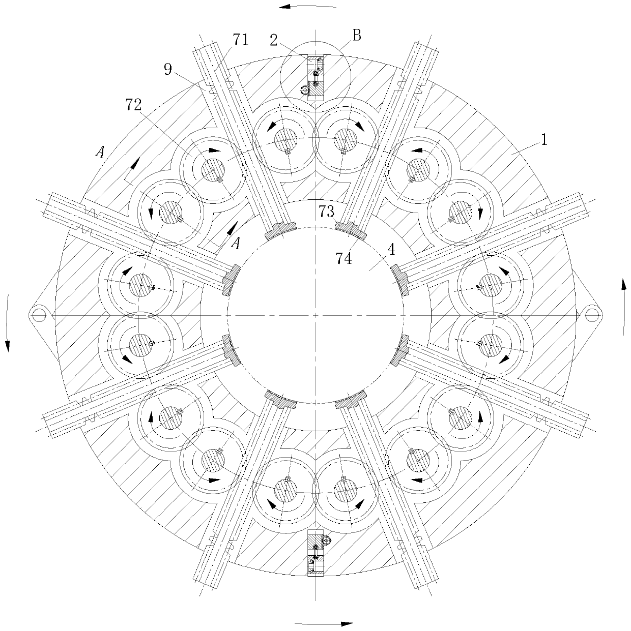
[0021] use Figure 1 to Figure 3 A high-precision rotating shaft fault detection and positioning device of the present invention is described as follows. figure 2 as the benchmark.

[0022] like Figure 1 to Figure 3 As shown, a high-precision rotating shaft fault detection and positioning device according to the present invention includes a shaft sleeve 1, a sound module 2, a labVIEW sound collection and analysis system and a controller; the shaft sleeve 1 is set on the rotating shaft to be measured 4, there is a No. 1 blind hole 3 on the outside of the shaft sleeve 1, and the number of No. 1 blind holes 3 is at least two. The No. 1 blind holes 3 are evenly distributed along the circumference of the shaft sleeve 1. The axis of the No. 1 blind hole 3 Along the radial direction of the shaft sleeve 1; the sound module 2 is located in the No. 1 blind hole 3, and the sound module 2 slides along the inner wall of the No. 1 blind hole 3; the sound module 2 includes a No. Spring ...


PUM


Abstract

The invention belongs to the technical field of high-speed precise rotating shaft detection equipment, and particularly relates to a high-precision rotating shaft fault detection and positioning device. The high-precision rotating shaft fault detection and positioning device comprises a shaft sleeve, sound production modules, a labVIEW sound collection and analysis system and a controller; the shaft sleeve sleeves a rotating shaft needing to be measured; at least two first blind holes are formed in the outer side of the shaft sleeve; the first blind holes are uniformly distributed in the circumferential direction of the shaft sleeve; the sound production modules are located in the first blind holes; the sound production modules slide along the inner walls of the first blind holes; and eachsound production module comprises a first sliding block, a sound production piece and a first spring. An upper shaft sleeve and a lower shaft sleeve can be separated, so that the rotating shaft can be measured under the condition that the rotating shaft of a machine is not detached; the sound production pieces are arranged on the shaft sleeve, and sounds of the sound production pieces are analyzed through the labVIEW sound collection and analysis system, so that a fault of the rotating shaft can be indirectly detected; and during detection, the labVIEW sound collection and analysis system does not need to be in contact with the rotating shaft.

Description

technical field [0001] The invention belongs to the technical field of high-speed precision rotating shaft detection equipment, in particular to a high-precision rotating shaft fault detection and positioning device. Background technique [0002] Precise testing equipment requires that the testing equipment have good stability when the equipment is running. In the high-speed rotating environment, the requirements for stability are higher, and the method to ensure the stability is mainly reflected in the verticality of the rotating shaft relative to the bottom plate and the rotating shaft after it is fixed. Concentricity with the motor shaft. [0003] The most traditional method is to simply install the rotating shaft and the bearing. If two radial bearings or one radial bearing and one thrust bearing are installed adjacent to each other, this method cannot well ensure the verticality and concentricity of the rotating shaft during operation. degrees, resulting in axis tilt o...

Claims


Application Information

Patent Timeline
Patent Type & Authority Applications(China)
IPC IPC(8): G01M13/028
CPCG01M13/028
Inventor 贾松丁赛赛张家俊
Owner 六安万邦机械科技有限公司