

Anchorage traction composite accessory and invisible correction device
A technology of invisible aligners and accessories, which is applied in the fields of medical science, dentistry, orthodontics, etc., can solve the problems of prolonged treatment time, loss of attachment function, anchorage function and traction function cannot coexist on the same attachment, and achieve Reduce the effect of experience dependence
- Summary
- Abstract
- Description
- Claims
- Application Information
AI Technical Summary
Problems solved by technology
Method used
Image

Examples
Embodiment 1
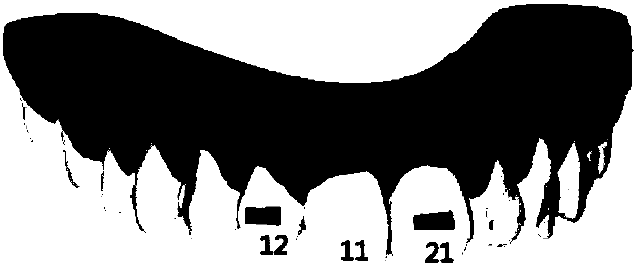
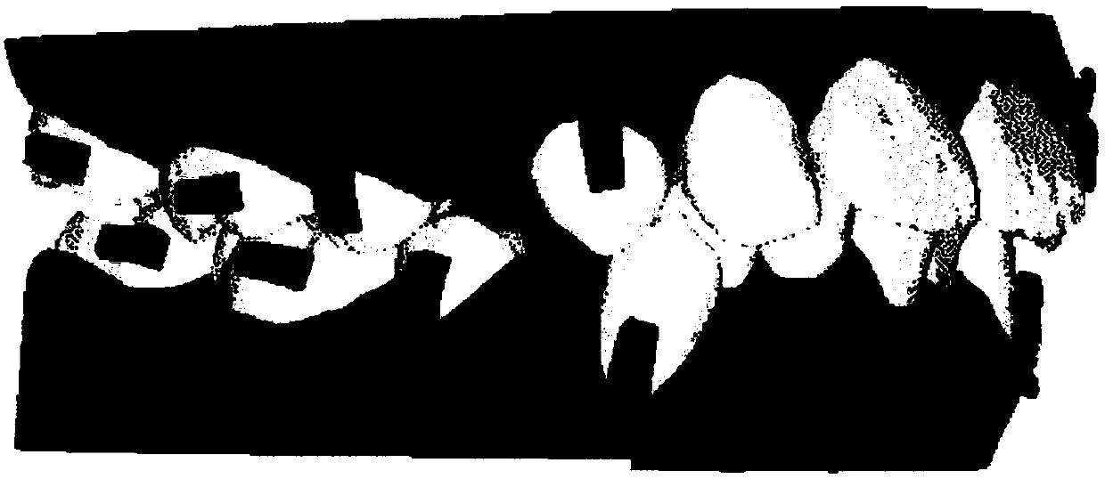
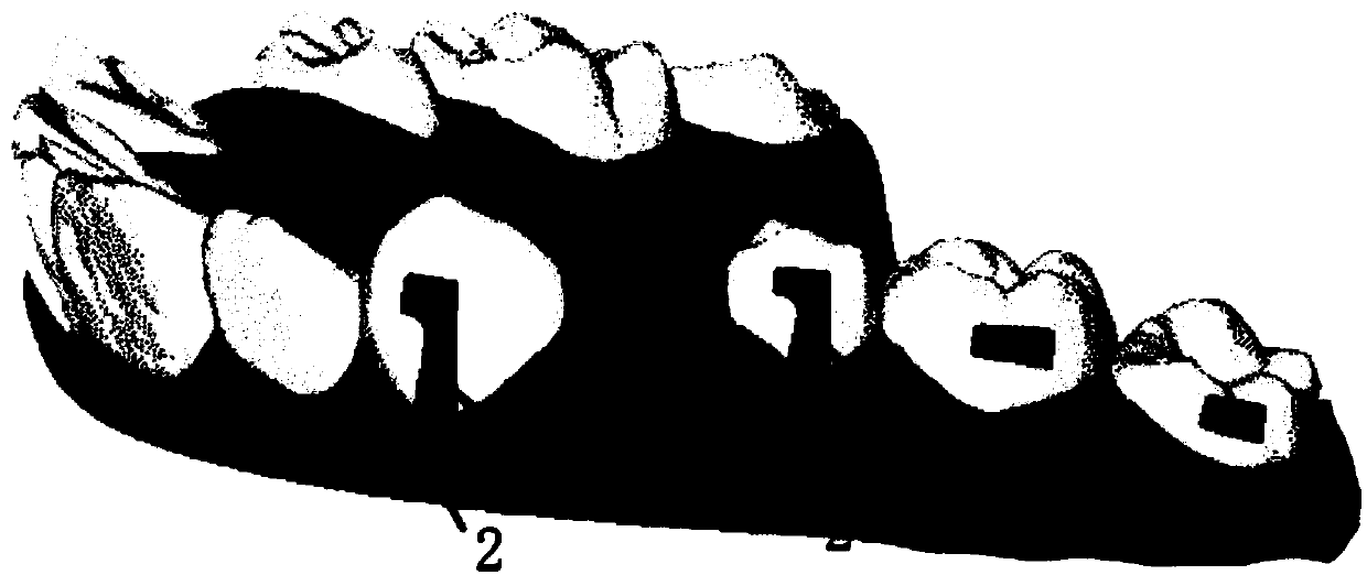
[0032] Anchorage traction compound accessories include body 1 and tow hook 2, body 1 and tow hook 2 are fixed, the hook of tow hook 2 is exposed, body 1 includes a mounting part for accommodating tow hook 2 and an anchorage part 1B that provides anchorage, The anchor portion 1B is located on the side of the mounting portion. When in use, the mounting part is downward, the anchorage part 1B is downward, and the anchorage part 1B faces the mesial direction of the dentition.
[0033] In some embodiments, such as image 3 with Figure 4 As shown, the main body 1 is L-shaped, the installation part is a vertical arm and the anchorage part 1B is a horizontal arm, the horizontal part is connected with the vertical part and protrudes toward one side, the horizontal part and the vertical part have a smooth transition, and the vertical part is connected with the traction hook 2 . The horizontal part realizes the anchorage function, and the vertical part serves as an installation site ...
PUM
 Abstract
Description
Claims
Application Information