Foldable wardrobe

A wardrobe and cabinet body technology, applied in wardrobes, cupboards, household appliances, etc., can solve the problems of single wardrobe structure and inconvenient folding, and achieve the effect of improving storage space and facilitating transportation and movement

Active Publication Date: 2019-08-27
ZHEJIANG LANYU INTELLIGENT TECH CO LTD
View PDF9 Cites 4 Cited by
  • Summary
  • Abstract
  • Description
  • Claims
  • Application Information

AI Technical Summary

Problems solved by technology

The wardrobe has a single structure and is not easy to fold

Method used


Image

  • Foldable wardrobe
  • Foldable wardrobe
  • Foldable wardrobe

Examples


specific Embodiment approach 1

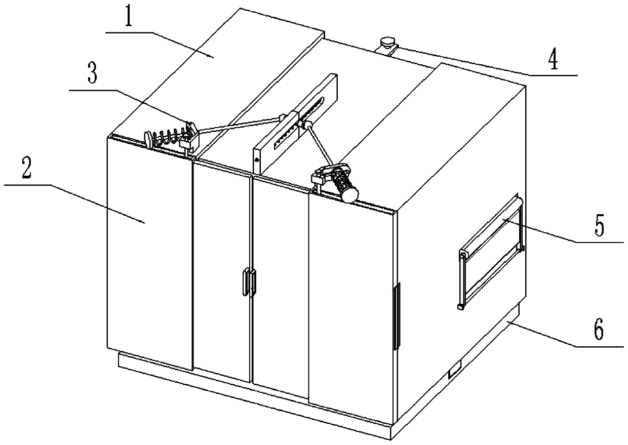
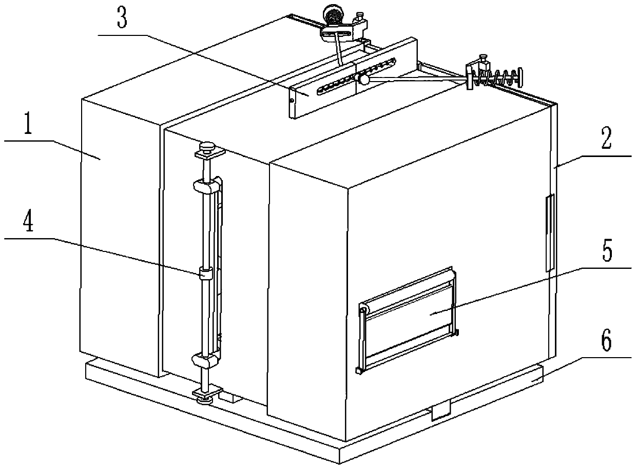
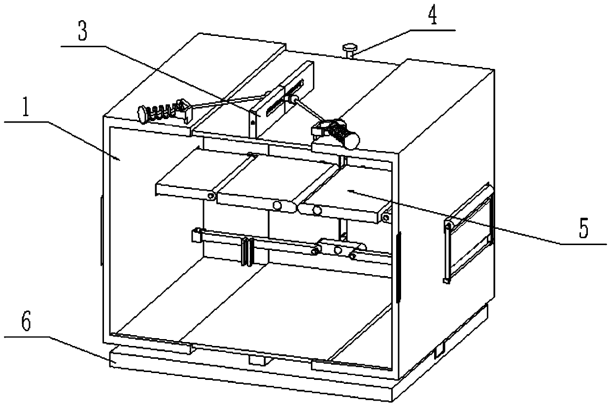
[0030] Such as Figure 1-12As shown, a foldable wardrobe includes a cabinet body assembly 1, a cabinet door assembly 2, a cabinet door limit assembly 3, a cabinet body control assembly 4, a shelf assembly 5 and a support 6, and the lower end of the cabinet body assembly 1 Connected on the support 6; the cabinet door assembly 2 is provided with two, the two cabinet door assemblies 2 are relatively arranged on the front end of the cabinet body assembly 1, and the outer ends of the two cabinet door assemblies 2 are respectively hingedly connected to the cabinet body assembly 1 the left and right ends of the front side; the cabinet door limit assembly 3 is fixedly connected to the middle of the top of the cabinet body assembly 1, and the left and right ends of the cabinet door limit assembly 3 are respectively connected to the inner ends of the two cabinet door assemblies 2; The middle end of the cabinet control assembly 4 is fixedly connected to the middle end of the cabinet asse...

specific Embodiment approach 2

[0033] Such as Figure 1-11 As shown, the cabinet assembly 1 includes a middle cabinet 1-1, a left cabinet 1-2, a right cabinet 1-3, a rectangular fixed block 1-4 and a rectangular slider 1-5; the middle cabinet The bottom end of 1-1 is fixedly connected to the rectangular fixed block 1-4, and the lower end of the rectangular fixed block 1-4 is fixedly connected to the middle of the top surface of the support 6; the left cabinet body 1-2 and the right cabinet body 1-3 Each of the bottom ends is fixedly connected with a rectangular slider 1-5, and the two rectangular sliders 1-5 are respectively slidably fitted and connected in two rectangular chute 6-1 on the top surface of the support 6; the middle cabinet body 1-1 The left and right ends of the left and right cabinets are respectively slidably connected to the inside of the left cabinet 1-2 and the right cabinet 1-3; the middle of the rear side of the middle cabinet 1-1 is provided with a vertical chute 1-1-1, and the left c...

specific Embodiment approach 3

[0035] Such as Figure 1-11 As shown, the cabinet door assembly 2 includes an inner cabinet door 2-1, an outer cabinet door 2-2, a handle 2-3 and a linkage shaft 2-4; the outer side of the outer cabinet door 2-2 is connected to the The left end of the left cabinet 1-2 or the right end of the right cabinet 1-3, the inner side of the outer cabinet door 2-2 is provided with an inner chute, the top of the outer cabinet door 2-2 is provided with an upper chute, and the inner chute is connected On the upper chute, the inner cabinet door 2-1 is connected to the inner side of the inner chute with clearance fit, the outer end of the top surface of the inner cabinet door 2-1 is fixedly connected to the linkage shaft 2-4, and the linkage shaft 2-4 is slidingly fitted and connected to the upper slide The inner side of the groove; the front end of the inner side of the inner cabinet door 2-1 is fixedly connected to the handle 2-3; When the cabinet door assembly 2 is in use, when the cabin...


PUM


Abstract

The invention relates to a wardrobe, in particular to a foldable wardrobe. The foldable wardrobe comprises a wardrobe body assembly, two wardrobe door assemblies, a wardrobe door limiting assembly, awardrobe body control assembly, a storage board assembly and a supporting seat, wherein the lower end of the wardrobe body assembly is connected to the supporting seat; the two wardrobe door assemblies are oppositely arranged at the front end of the wardrobe body assembly, and the outer ends of the two wardrobe door assemblies are separately hinged to the left end and the right end of the front side of the wardrobe body assembly; the wardrobe door limiting assembly is fixedly connected in the middle of the top end of the wardrobe body assembly, and the left end and the right end of the wardrobe door limiting assembly are separately connected with the inner ends of the two wardrobe door assemblies; and the middle end of the wardrobe body control assembly is fixedly connected with the middleend of the wardrobe body assembly, and the left end and the right end of the wardrobe body control assembly are separately and fixedly connected with the left end and the right end of the wardrobe body assembly. The foldable wardrobe can be folded, is convenient to use in places with narrow space, can be unfolded for use, can accommodate more clothes after being unfolded, and increases the storage space.

Description

technical field [0001] The invention relates to a wardrobe, in particular to a foldable wardrobe. Background technique [0002] The structure of the existing wardrobe is relatively simple, and it is not easy to fold. For example, the patent No. is a cloth wardrobe of CN200920085775.8, which specifically relates to a cloth wardrobe with a variable travel bag. It includes a wardrobe frame, which is formed by connecting a three-way joint and a two-way joint. Two wardrobe covers, the top of the lower wardrobe cover cooperates with the zipper on the top of the upper wardrobe cover through a zipper, when the upper wardrobe cover and the lower wardrobe cover are matched up and down, the overall height is equal to the total height of the wardrobe frame minus the height of the feet, and the lower wardrobe The four corners of the bottom of the cover are provided with four assembly holes, and the four legs exposed at the bottom of the wardrobe skeleton are configured with the assembly...

Claims


Application Information

Patent Timeline
Patent Type & Authority Applications(China)
IPC IPC(8): A47B61/00A47B96/00
CPCA47B61/00A47B96/00
Inventor 不公告发明人
Owner ZHEJIANG LANYU INTELLIGENT TECH CO LTD
Why Eureka
Try Eureka