Tapering component

A mold assembly and the same technology, applied in the field of draft assembly, can solve the problems of difficulty in demoulding, can not be demolded smoothly, etc., and achieve the effect of convenient mold assembly

Inactive Publication Date: 2019-08-27
苏州市群友精密机械有限公司
View PDF6 Cites 0 Cited by
  • Summary
  • Abstract
  • Description
  • Claims
  • Application Information

AI Technical Summary

Problems solved by technology

[0005] The purpose of the present invention is to provide a draft assembly to solve the above-mentioned background technology. When manufacturing products through molds, some products will have some protruding parts, such as buckle parts, connectors, etc. For parts at these positions, It is usually necessary to make modules for it. In order to adapt to the shape of these parts and products, these modules are provided with some small bosses, but due to the existence of these bosses, it is difficult to demould. When the module is demolded, the path is set to When facing to the left, the boss will touch the equipment or parts on other molds, and when it is set to face down, it will not be able to demould smoothly

Method used


Image

  • Tapering component
  • Tapering component
  • Tapering component

Examples


Embodiment

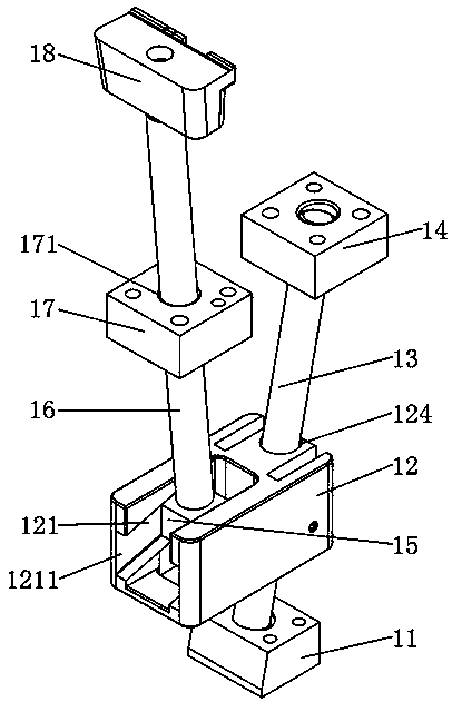
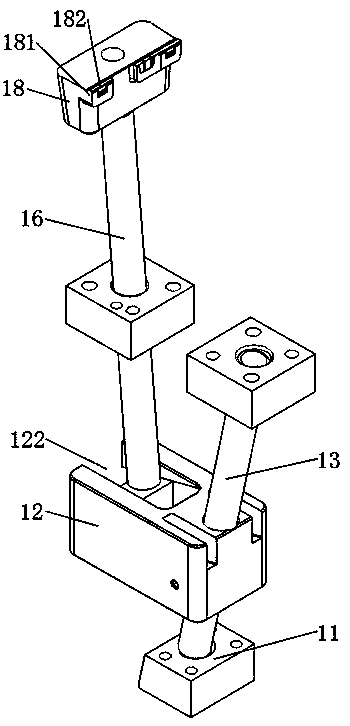
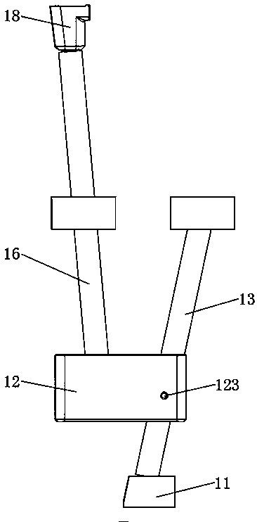
[0022] see Figure 1-4 , the present invention provides a technical solution: a draft assembly, including a first fixed block 11, a second fixed block 14 and a third fixed block 17, the top of the first fixed block 11 and the second fixed block 14 A guide rod 13 is installed between the bottoms, and the connecting block 12 for sliding connection is sleeved on the guide rod 13, and the inside of the connecting block 12 has a first through hole 124 matched with the guide rod 13 , the first fixing block 11 and the second fixing block 14 are not on the same vertical plane, the top of the connecting block 12 is provided with a gap 122, and the inside of the connecting block 12 is away from a part of the first through hole 124 The short side is provided with an inclined chute 121, the chute 121 has an opening 1211, a slider 15 is slid in the chute 121, an inclined connecting rod 16 is provided on the top of the slider 15, and the third fixed The top of the block 17 is provided with...


PUM


Abstract

The invention discloses a tapering component. The tapering component comprises a first fixed block, a second fixed block and a third fixed block, wherein a guide rod is arranged between the top of thefirst fixed block and the bottom of the second fixed block and is in sleeve connection with a connecting block being in slip connection; a first through hole matched with the guide rod penetrates theinterior of the connecting block; the first fixed block and the second fixed block are not on the same vertical plane; an opening is formed in the top of the connecting block; when the mold release is required, the connecting block is controlled to slide on the guide rod toward the direction of the first fixed block; in the downward sliding process of the guide rod, a sliding block slides along asliding chute toward the direction far away from the opening, so that the connecting rod slides in a second through hole, at the moment a module also moves in succession, a boss of the module avoidstouching other components, and thus, the tapering is realized quickly and conveniently. When the mold needs to be spliced, a user controls the connecting block and the sliding block in the opposite direction, so that the mold splicing can be realized quickly and easily.

Description

technical field [0001] The invention relates to the technical field for connecting or removing objects that are press-fitted, in particular to a draft assembly. Background technique [0002] Draft is usually used to add a slope to the vertical face of a model, part, mold or die so that the part or model is separated from its mold or die by means of a draft surface, in order to remove the wooden form from the sand without To destroy the sand mold, the blank design of the part often has a taper with a large top and a small bottom, which is called the draft angle. There are three forms of draft angle: increasing thickness method, adding and subtracting thickness method, and reducing thickness method. [0003] There are following problems in prior art: [0004] When manufacturing products through molds, some products will have some protruding parts, such as buckle parts, connecting bodies, etc. For these parts, it is usually necessary to make modules for them. In order to adap...

Claims


Application Information

Patent Timeline
Patent Type & Authority Applications(China)
IPC IPC(8): B22D29/04
CPCB22D29/04
Inventor 李全杰刘斌
Owner 苏州市群友精密机械有限公司
Why Eureka
Try Eureka