Boundary configurations for multi-material print-forming

Inactive Publication Date: 2010-01-14
EOPLEX
View PDF18 Cites 61 Cited by
  • Summary
  • Abstract
  • Description
  • Claims
  • Application Information

AI Technical Summary

Benefits of technology

[0026]Another object of the present invention is to provide a structure formed of dissimilar materials which resists warping.
[0027]Another object of the present invention is to provide a structure of dissimilar materials which distributes stress over a large region between dissimilar materials, rather than concentrating stresses along a boundary.
[00

Problems solved by technology

However, such homogeneous structures are suitable only for the most basic technology and cannot produce the sophisticated results required in many applications.
Many processes address some of the requirements in this area but none are able to cover all the requirements and some devices remain either impossible to mass produce, cost prohibitive or both.
However, there are very few technologies that can handle several different materials simultaneously, with complex geometries, in small parts.
In particular, and as depicted in FIG. 4, the material A does not expand as much as the material D. While the materials A, D are joined together at the boundary B, and thus have a tendency to restrain expansion under the thermal stress associated with application of the heat H, these stresses can exceed limits of the materials, resulting in undesirable warping and/or the formation of cracks C. In severe cases the materials can even split apart at the junction.
Concentration of thermal stresses along a bou

Method used


Image

  • Boundary configurations for multi-material print-forming
  • Boundary configurations for multi-material print-forming
  • Boundary configurations for multi-material print-forming

Examples


Embodiment Construction

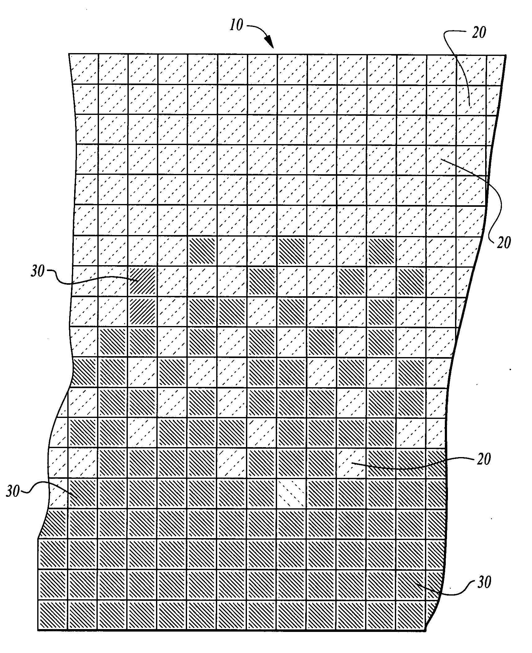
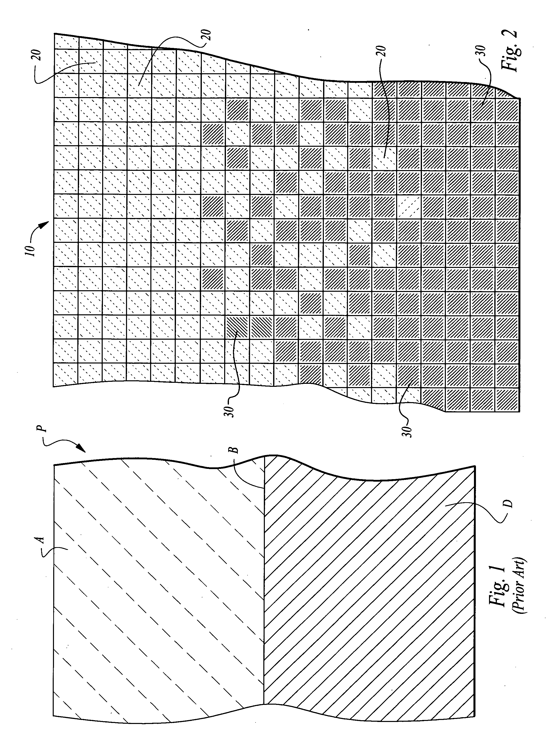
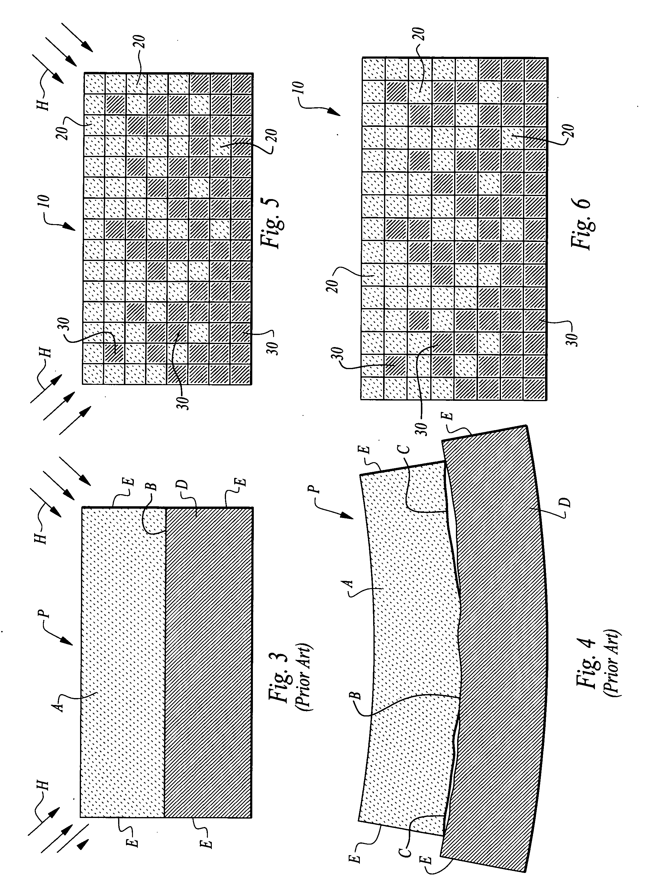
[0050]Referring to the drawings, wherein like reference numerals represent like parts throughout the various drawing figures, reference numeral 10 is directed to a structure (FIG. 2) that is formed of two different materials. The two materials come together at a boundary region with one of the materials comprising first micro-bricks 20 and one of the materials comprising second micro-bricks 30. The first micro-bricks 20 and second micro-bricks 30 are largely confined to separate regions adjacent each other at the boundary region. Within the boundary region, various different transitional schemes are employed to gradually transition from substantially only the first material to substantially only the second material. In this way, dissimilarities in the performance of the materials do not result in concentration of stresses and otherwise sharp differences in material performance at the boundary. Rather, any such stresses are dispersed so that less overall stress and propensity to fail...


PUM

PropertyMeasurementUnit
Timeaaaaaaaaaa
Concentrationaaaaaaaaaa
Structureaaaaaaaaaa

Abstract

A print-forming method is disclosed which provides a method to engineer and design boundaries between the materials used in devices. The boundary includes primarily a first material on one side and primarily a second material on the other side. At least some of the second material is located on the first material side of the boundary and at least some of the first material is located on the second material side of the boundary in a precise pattern that achieve the objectives of the design. This approach is then extended to 3-dimensional shapes with any number of materials. Material properties that differ from each other thus do not exhibit an abrupt transition within the overall structure, but rather are accommodated within the boundary region. Various different exemplary boundary region configurations are disclosed, as well as techniques for optimizing this print-forming manufacturing within boundary regions.

Description

CROSS-REFERENCE TO RELATED APPLICATIONS[0001]This application incorporates by reference U.S. Pat. No. 5,348,693 and U.S. Pat. No. 7,255,551 in their entirety.FIELD OF THE INVENTION[0002]The following invention relates to structures which are formed by printing of layers of the material from which the structure is to be formed in successive layers, with typically multiple similar parts being manufactured simultaneously. More particularly, this invention relates to structures which include two or more dissimilar materials and methods for configuring boundaries between the dissimilar materials to minimize detrimental effects associated with interaction of the dissimilar materials with each other and a surrounding environment at the boundary.BACKGROUND OF THE INVENTION[0003]A manufacturing technology pioneered by the applicant is known in the prior art by the term “print-forming.” Examples of this prior art technology are described in U.S. Pat. Nos. 5,348,693 and 7,255,551, incorporated...

Claims


Application Information

Patent Timeline
IPC IPC(8): B32B3/10B05D1/36
CPCA63F2009/1083Y10T428/24802B29C67/0059B29C64/112B33Y10/00
Inventor CHAIT, ARTHUR L.
Owner EOPLEX
Why Eureka
Try Eureka