Suspension for mounting magnetic head slider, head gimbal assembly and hard disk drive

Inactive Publication Date: 2006-12-28
SAE MAGNETICS (HK) LTD
View PDF6 Cites 22 Cited by
  • Summary
  • Abstract
  • Description
  • Claims
  • Application Information

AI Technical Summary

Benefits of technology

[0018] By providing a plurality of slit-type holes of the same shape or different shapes as described above, the number of end-part areas with the spring characteristic in the longitudinal direction of the slits is increased on the tongue face, and the stress can be dispersed as well. Thus, deformation of the tongue face by thermal expansion can be absorbed more. Particularly, by forming each slit-type hole in such a manner that the centers of slit-type holes adjacent to each other are not arranged on almost the same straight line with respect to the longitudinal direction of the tongue face or by setting the space between the slit-type holes, it is possible to absorb the deformation more effectively while maintaining the strength of the tongue face.
[0019] Further, another form of the present invention is a head gimbal assembly comprising the above-described suspension. Furthermore, still another

Problems solved by technology

Furthermore, even with the use of a low-elastic epoxy adhesive that absorbs the thermal expansion difference of both members as disclosed in Patent Literature 1, it is not possible to cope with such deformation caused by an expansion difference of such an extent that cannot be absorbed by the adhesive.
Particularly, this is not

Method used


Image

  • Suspension for mounting magnetic head slider, head gimbal assembly and hard disk drive
  • Suspension for mounting magnetic head slider, head gimbal assembly and hard disk drive
  • Suspension for mounting magnetic head slider, head gimbal assembly and hard disk drive

Examples


Example

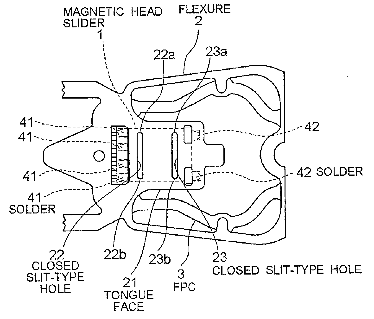
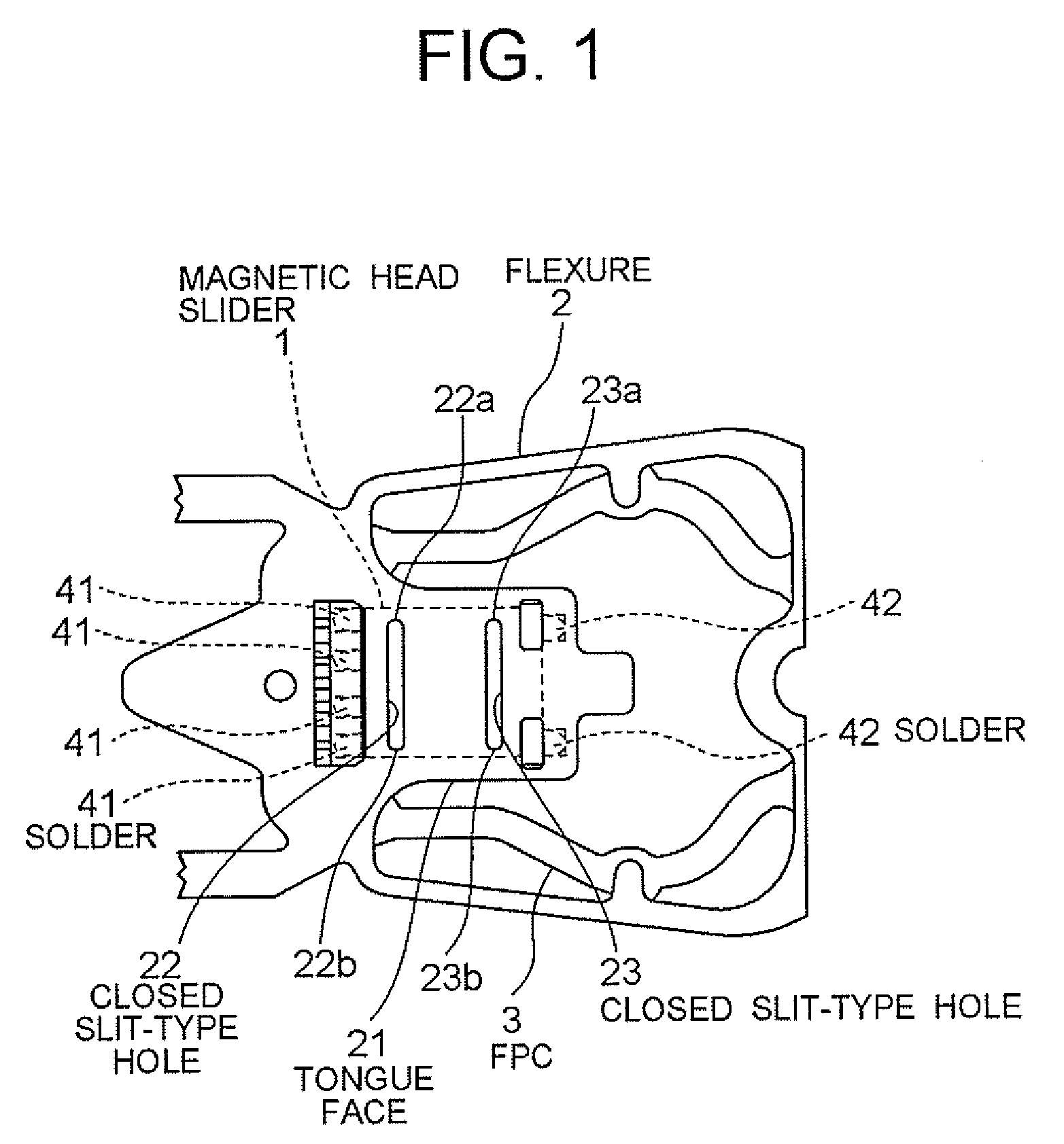
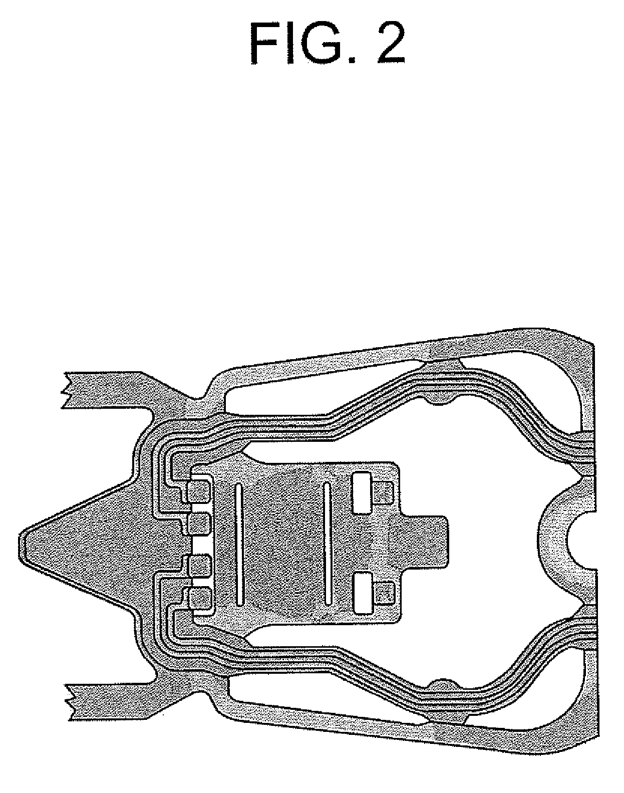
[0034] A first embodiment of the present invention will be described by referring to FIG. 1, FIG. 2, FIG. 8 and FIG. 9. FIG. 1 is an illustration for showing the structure of a suspension, and FIG. 2 is a stress contour when heated. FIG. 8 is an illustration for showing the structure of a head stack assembly that comprises a plurality of head gimbal assemblies to which the suspension is mounted, and FIG. 9 shows the structure of a hard disk drive to which the structure of FIG. 8 is loaded.

[Structure]

[0035]FIG. 1 shows the shape of a flexure 2 as a part of the suspension to which a magnetic head slider 1 is mounted. As shown in FIG. 8, the flexure 2 is fixed to a load beam 11 and, further, the load beam 11 is fixed to a base plate 12 for constituting a suspension 13. Further, the suspension 13 in such constitution is mounted on a head arm 14 through the base plate 12 for constituting a head gimbal assembly 10. Furthermore, each head arm 14 of a plurality of head gimbal assemblies 1...

Example

Second Embodiment

[0050] Next, a second embodiment of the present invention will be described by referring to FIG. 3 and FIG. 4. In this embodiment, the shape and position of the slit hole 24 formed in the tongue face 21 are different from those of the case described in the first embodiment.

[Structure]

[0051] As shown in FIG. 3, in this embodiment, there are formed slit-type holes 24 that are cut into the center from the ends on both sides of the tongue face 21. That is, this slit-type hole 24 is formed by being cut from the side-end of the tongue face 21 to be in a shape whose one end is open. In other words, it is separately formed into slit-type holes 24a and 24b, opening respectively towards the both side-ends from the vicinity of the center of the tongue face 21. Thus, end parts 24aa and 24ba of the respective sits in the longitudinal direction are positioned in the vicinity of the center of the tongue face 21, and the top-end side and the rear-end side of the tongue face 21 a...

Example

Third Embodiment

[0057] Next, a third embodiment of the present invention will be described by referring to FIG. 5 and FIG. 6. In this embodiment, the slit-type holes 22, 23 and 24 described in the first and second embodiments are combined. The detailed description will be provided hereinafter.

[Structure]

[0058] As shown in FIG. 5, in this embodiment, four slit-type holes 22, 23 and 24 (24a, 24b) are formed in the tongue face 21. Specifically, first, the closed slit-type holes 22 and 23 having the end parts 22a, 22b, 23a, 23b on the side-ends of the tongue face 21 described in the first embodiment are formed in the vicinity of the top end (in the vicinity of the base) of the tongue face 21 and in the vicinity of the rear end, respectively. Further, in almost the center in the longitudinal direction of the tongue face 21, there are formed a pair of one-end-open slit-type holes 24 (24a, 24b) which are formed by being cut from both side-ends towards the inner side and separated at the...


PUM


Abstract

There is provided a suspension capable of suppressing deformation of a magnetic head slider mounted thereon. At the same time, there are provided high-quality head gimbal assembly and hard disk drive capable of achieving stable writing and reading of data. It is a suspension comprising a tongue face for mounting a magnetic head slider, wherein a deformation-difference absorbing device is provided on the tongue face for absorbing a difference between thermal deformations of the tongue face and the magnetic head slider.

Description

BACKGROUND OF THE INVENTION [0001] 1. Field of the Invention [0002] The present invention relates to a suspension for loading a magnetic head slider and, more specifically, to a suspension capable of suppressing deformation of a magnetic head slider that is loaded thereon. Furthermore, the present invention relates to a head gimbal assembly and a hard disk drive which comprise the suspension. [0003] 2. Description of the Related Art [0004] A head gimbal assembly to be loaded on a hard disk drive comprises a suspension for mounting a magnetic head slider that performs writing and reading of data to / from a magnetic disk. The suspension comprises a flexure 102 to which a magnetic head slider 101 is directly mounted. FIG. 10 shows the tip part of the flexure 102. FIG. 10A illustrates the top-face side of the flexure 102 on which the magnetic head slider is mounted, whereas FIG. 10B shows the back-face side thereof. [0005] As shown in FIG. 10A, the flexure 102 of the conventional case ha...

Claims


Application Information

Patent Timeline
IPC IPC(8): G11B5/48G11B21/16
CPCG11B5/4826
Inventor HONDA, TAKASHI
Owner SAE MAGNETICS (HK) LTD
Why Eureka
Try Eureka