
Terminal connection structure and method for producing same

Active Publication Date: 2017-05-18
DIAMOND&ZEBRA ELECTRIC MFG CO LTD
View PDF0 Cites 1 Cited by
  • Summary
  • Abstract
  • Description
  • Claims
  • Application Information

AI Technical Summary

Benefits of technology

The present invention provides a terminal connection structure and a method for producing it that prevents damage to the electric wire end portion and ensures high mechanical reliability. The structure has a gentle curved surface that disperses stress acting between the first and second end sections, preventing breakage. The method for producing the structure involves pressing the electric wire end portion with a curved surface shape or tapered surface shape electrodes to disperse stress and prevent breakage. Additionally, the method ensures a good solder connection state by heating the electric wire end portion with a gentle curved surface shape and introducing solder and flux into the terminal main part.

Problems solved by technology

However, in general, in a case where an aluminum electric wire is connected to a copper-alloy terminal, an aluminum wire in the terminal does not reach a predetermined necessary temperature due to low heat conductivity of the copper-alloy terminal even when the terminal is heated in soldering.
It is therefore undesirably hard to introduce a flux or molten solder into the whole of the inside of the terminal.
This results in formation of voids in the solder and parts that are not soldered, thereby causing a problem that the reliability of electrical joining becomes low.
The voids can be a cause of discharge, occurrence of electric erosion, an increase of electric resistance, generation of heat during application of electricity, and the like and are therefore not desirable.
Meanwhile, in a case where the terminal and an end of the electric wire are compressed by swaging with great force in order to reduce voids and improve thermal conductivity, there is a risk of damaging of the electric wire and even breaking of the electric wire.

Method used


Image

  • Terminal connection structure and method for producing same
  • Terminal connection structure and method for producing same
  • Terminal connection structure and method for producing same

Examples


Embodiment Construction

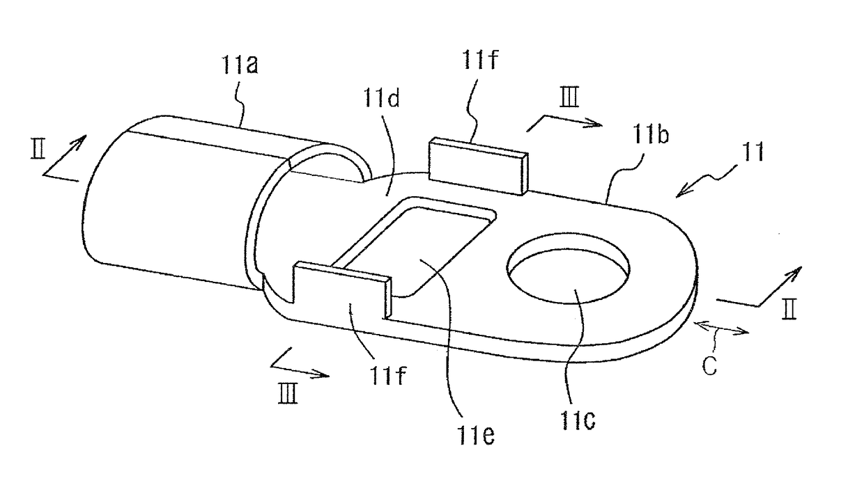
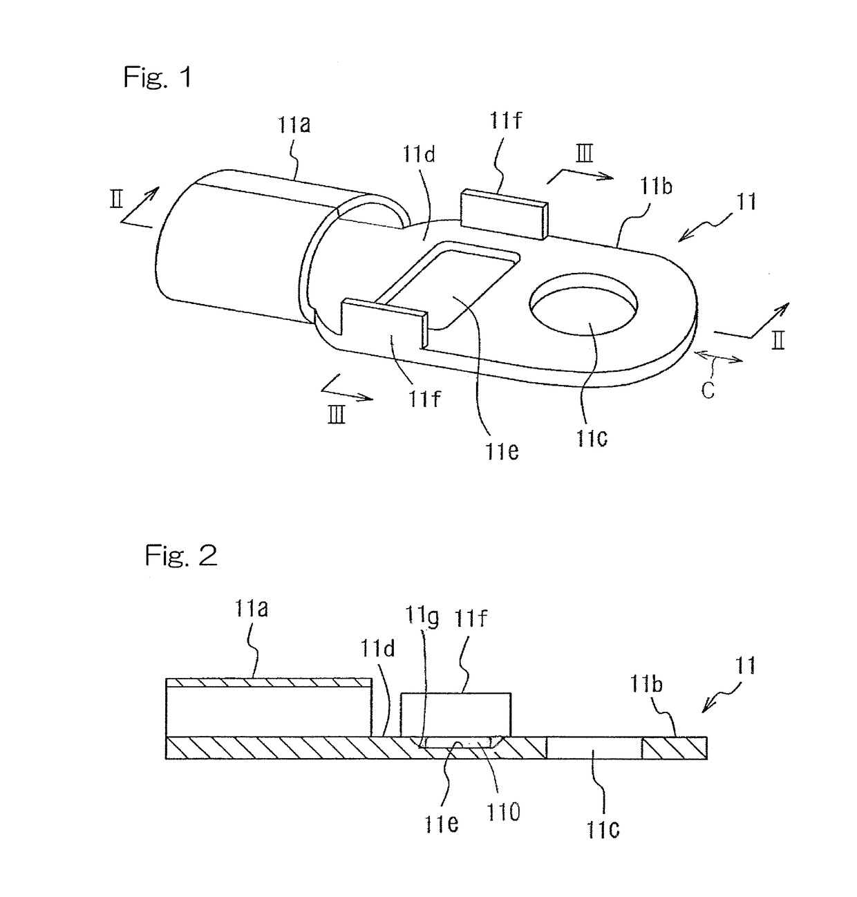
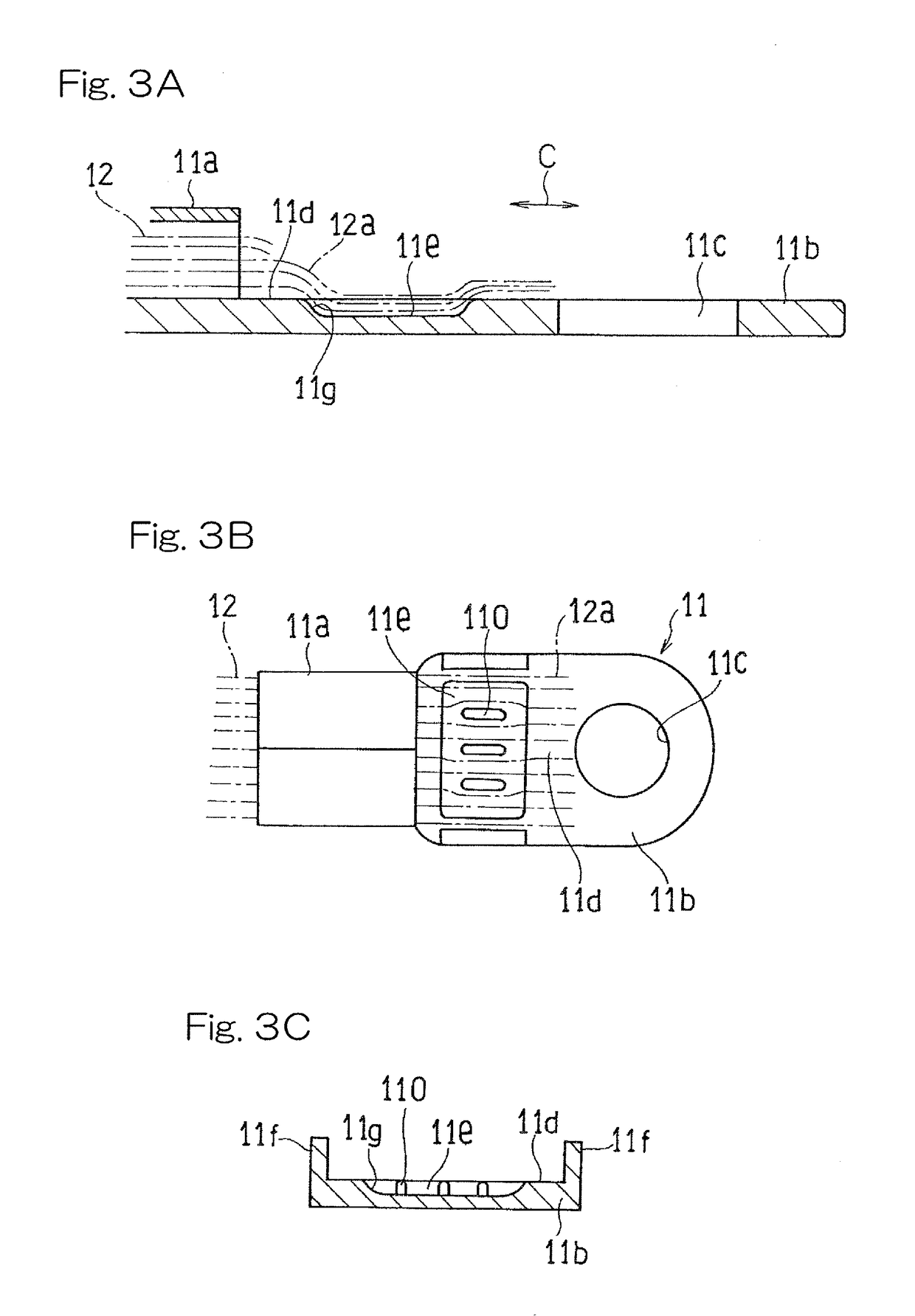
[0052]A method for producing a terminal connection structure for an electric wire end portion and the terminal connection structure according to an embodiment of the present invention are described below. A terminal 11 in the terminal connection structure is described with reference to FIGS. 1 to 3C. The terminal 11 includes a tubular terminal main part 11a and a terminal piece 11b having a flat-plate shape that is continuous with a front end side of the terminal main part 11a. The terminal 11 is formed from a plate material made of copper, brass, a copper alloy, or a copper-based composite material. The terminal piece 11b has a terminal hole 11c. The terminal 11 has a metal plating layer (not illustrated) made of tin or solder that is provided on at least a surface of inside of the terminal main part 11a. A recess 11e is provided in a soldering surface 11d, which is a top surface of the terminal piece 11b, and a pair of restricting walls 11f are provided along both side edges of th...


PUM


Abstract

A terminal connection structure for an electric wire end portion (12a) in which the electric wire end portion is soldered being exposed on a flat-plate terminal piece (11b) out from inside of a terminal main part (11a), the terminal piece being continuous with a front end of the terminal main part (11a). The electric wire end portion (12a) exposed on the terminal piece (11b) from the terminal main part (11a) includes a first end section (12a1) that is close to the terminal main part (11a) and a second end section (12a2) that is far from the terminal main part (11a). The electric wire end portion (12a) has a shape, in side view, such that the first end section (12a1) is compressed to have a gentle curved surface that approaches the terminal piece (11b) toward the second end section (12a2).

Description

CROSS REFERENCE TO THE RELATED APPLICATION[0001]This application is a continuation application, under 35 U.S.C. §111 (a) of international application No. PCT / JP2014 / 070260, filed Jul. 31, 2014.BACKGROUND OF THE INVENTION[0002]Field of the Invention[0003]The present invention relates to a terminal for aluminum electric wire connection and a method for producing the same.[0004]Description of Related Art[0005]In recent years, there are increasing demands for an aluminum electric wire, which is light in weight and low in cost, for the purpose of achieving both an improvement of energy efficiency and a reduction of cost. In a case where this electric wire having the above characteristics is connected to an electric apparatus, means for connecting copper and aluminum is needed because a wire in the electric apparatus is copper in many cases, and a copper-alloy terminal is often used as such means. Various methods such as a method using soldering, a method using an ultrasonic wave, a metho...

Claims


Application Information

Patent Timeline
IPC IPC(8): H01R4/02H01R43/02H01R4/62
CPCH01R4/024H01R2101/00H01R43/02H01R4/625H01R9/03H01R11/12H01R13/58H01R43/0235
Inventor KUNIMI, TAKENORI
Owner DIAMOND&ZEBRA ELECTRIC MFG CO LTD
Learn More