
Sub-module fault diagnosis method of modular multilevel converter
A modular multi-level, fault diagnosis technology, applied in the field of power transmission and distribution, can solve problems such as undiagnosable fault diagnosis ability, complex hardware circuit design, etc.
- Summary
- Abstract
- Description
- Claims
- Application Information
AI Technical Summary
Problems solved by technology
Method used
Image

Examples
Embodiment Construction
[0054] The preferred embodiments are described in detail below in conjunction with the drawings. It should be emphasized that the following description is only exemplary, and is not intended to limit the scope and application of the present invention.
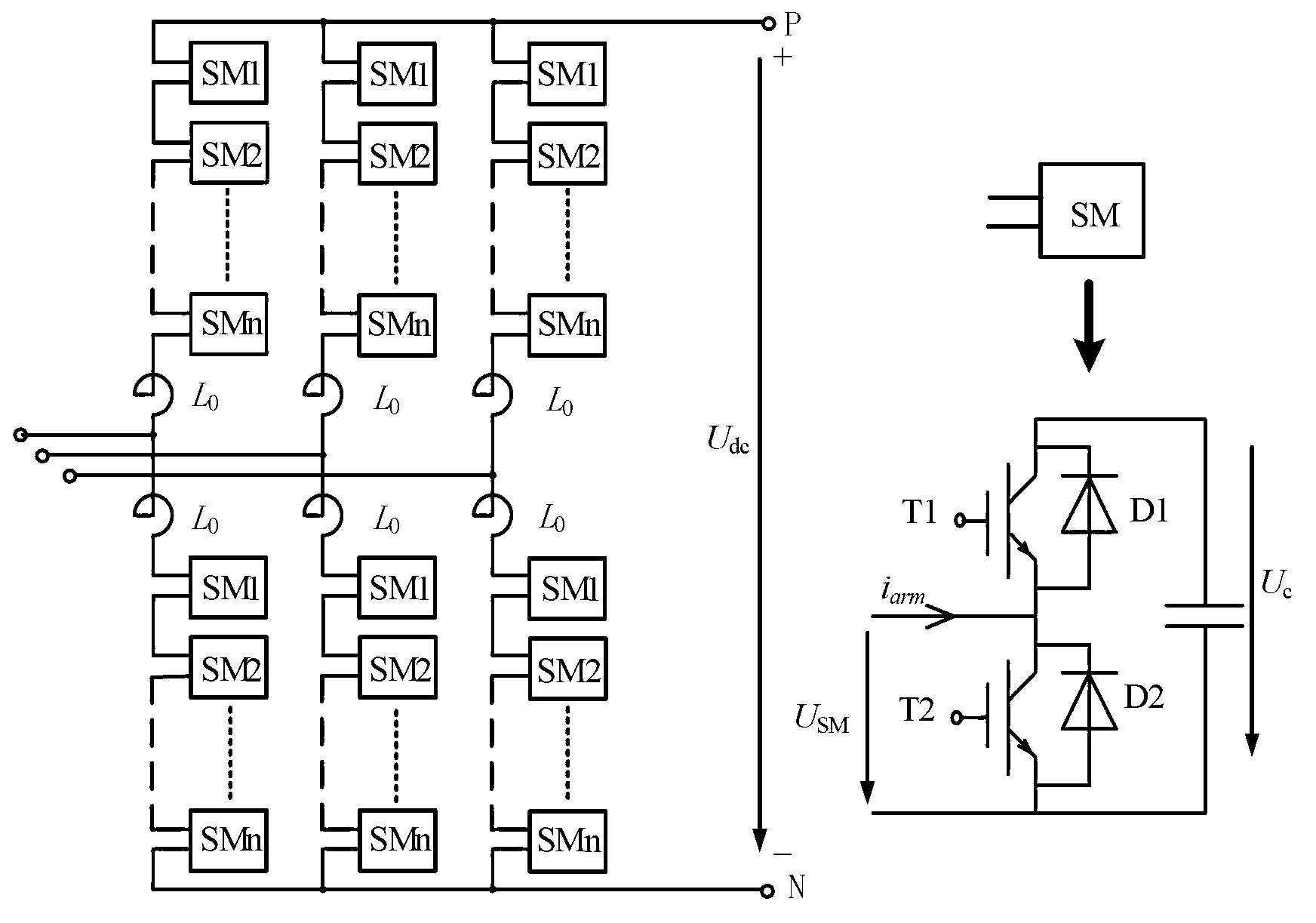
[0055] figure 1 The topological structure diagram of the modular multilevel converter MMC (half bridge) provided by the present invention. figure 1 Among them, SM1, SM2,..., SMn, represent the first submodule, the second submodule,..., the nth submodule in a bridge arm of MMC; L 0 Represents the bridge arm reactor; U dc Indicates the voltage difference between the positive and negative DC buses of the MMC. T1, T2 respectively represent the upper and lower IGBTs in the half-bridge submodule, D1, D2 respectively represent the anti-parallel diodes of the corresponding IGBTs; i arm Is the bridge arm current; C 0 Represents the capacitor in the half-bridge sub-module; U c Indicates the capacitor voltage of the sub-module; U SM Indi...
PUM
 Abstract
Description
Claims
Application Information