Device for adjusting height of galvanometer

A height adjustment and adjustment block technology, which is applied in welding equipment, laser welding equipment, metal processing equipment, etc., can solve the problems of unbalanced height, insufficient precision of self-made fine thread, and high cost, so as to reduce costs, reduce parts, The effect of enhancing stability

Pending Publication Date: 2019-09-06
南京魔迪多维数码科技有限公司
View PDF0 Cites 0 Cited by
  • Summary
  • Abstract
  • Description
  • Claims
  • Application Information

AI Technical Summary

Problems solved by technology

For multi-station laser equipment, the number of galvanometers is equal to the number of stations, and these galvanometers are all fixed on the same Z-axis, but the galvanometers cannot be unified due to the error of the hole position and the gap between the threads during the fixing process. height, so a height adjustment is required for a single galvanometer
The existing height adjustment technology basically uses sliders and rails, and then adjusts with self-made fine-pitch threads. Such a structure is expensive and the precision of self-made fine-pitch threads is not enough.

Method used


Image

  • Device for adjusting height of galvanometer
  • Device for adjusting height of galvanometer
  • Device for adjusting height of galvanometer

Examples


Embodiment Construction

[0020] The following will clearly and completely describe the technical solutions in the embodiments of the present invention with reference to the accompanying drawings in the embodiments of the present invention. Obviously, the described embodiments are only some, not all, embodiments of the present invention.

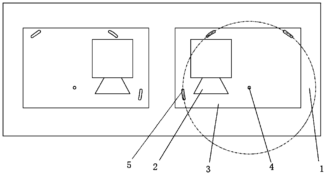
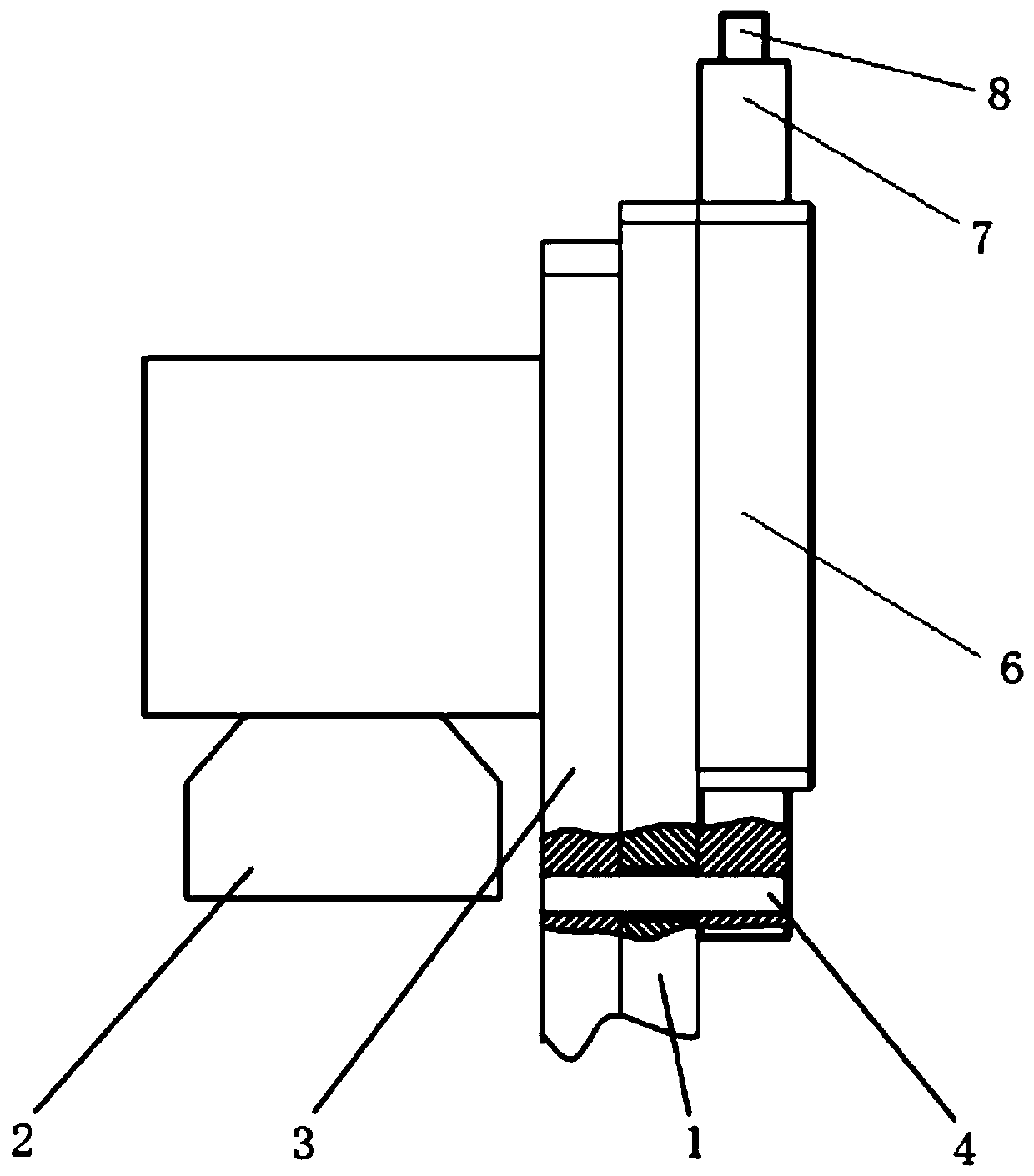
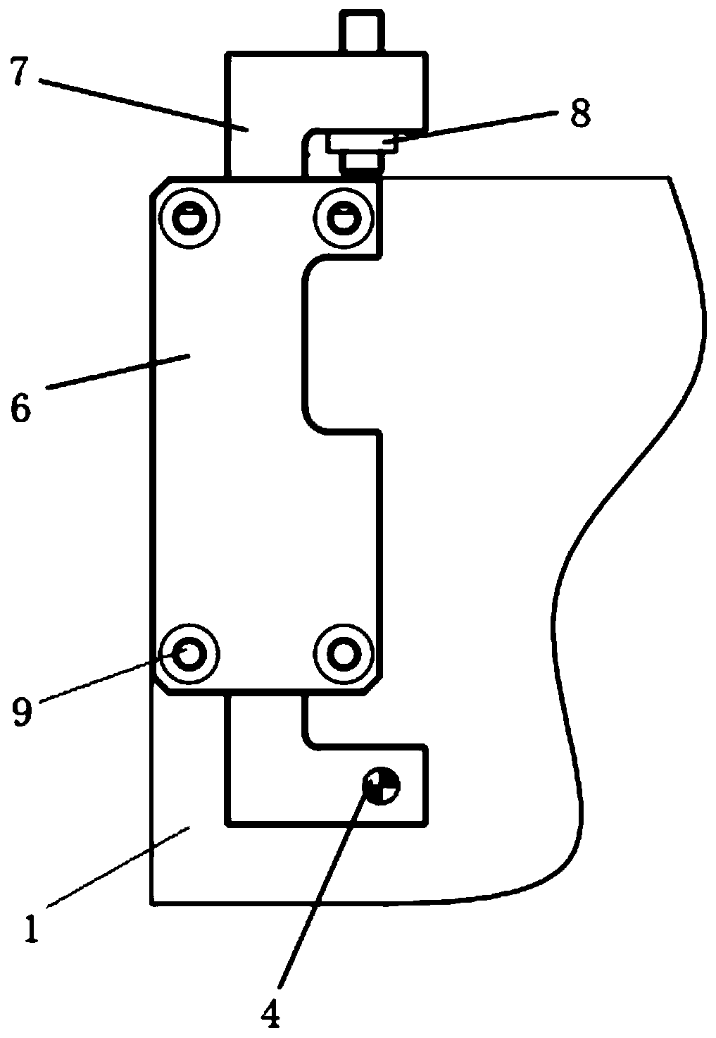
[0021] refer to Figure 1-3 , a device for adjusting the height of the vibrating mirror, including a Z-axis base plate 1, a vibrating mirror base plate 3, and a vibrating mirror 2 installed on the vibrating mirror base plate 3, and a vibrating mirror pin is provided on the back of the vibrating mirror base plate 3 at the side of the vibrating mirror 2 hole, the position corresponding to the galvanometer pin hole on the Z-axis bottom plate 1 is provided with an adjustment through hole, and one end of the pin shaft 4 is transitionally fitted in the galvanometer pin hole, and the middle part of the pin shaft 4 is clearance fit in the adjustment through hole. In the hole...


PUM


Abstract

The invention belongs to the technical field of laser processing, and particularly discloses a device for adjusting the height of galvanometers. The device comprises a Z-axis bottom plate, galvanometer bottom plates and the galvanometers mounted on the galvanometer bottom plates. Galvanometer pin holes are formed in the positions, located on the side faces of the galvanometers, of the back faces of the galvanometer bottom plates. Adjusting through holes are formed in the positions, corresponding to the galvanometer pin holes, of the Z-axis bottom plate. One end of a pin shaft is arranged in each galvanometer pin hole in a transition fit manner. The middles of the pin shafts are arranged in the adjusting through holes in a clearance fit manner. Adjusting blocks are arranged at the other ends of the pin shafts in a transition fit manner. The upper ends of the adjusting blocks extend to the upper portion of the Z-axis bottom plate. Differential adjusting screws are mounted at the upper ends of the adjusting blocks. Multiple processing through holes are formed in the galvanometer bottom plates. Threaded holes corresponding to the processing through holes are formed in the Z-axis bottomplate. Half-thread bolts are arranged in the processing through holes. One ends of the half-thread bolts are arranged in the threaded holes in a threaded fit manner. The height of the galvanometers is adjusted, and meanwhile angle adjustment of other planes of the galvanometers is not influenced.

Description

technical field [0001] The invention relates to the technical field of laser processing, in particular to a device for adjusting the height of a vibrating mirror. Background technique [0002] The galvanometer is an optical component used in laser processing equipment. The laser beam is injected into the galvanometer, adjusted by the servo motor in the galvanometer, and then directed to the workpiece for processing. At present, most of the laser processing equipment using galvanometers on the market are single-station, which uses a single galvanometer for processing. In this case, the height adjustment of the galvanometer can be completed by moving up and down the Z-axis. For multi-station laser equipment, the number of galvanometers is equal to the number of stations, and these galvanometers are all fixed on the same Z-axis, but the galvanometers cannot be unified due to the error of the hole position and the gap between the threads during the fixing process. height, so a ...

Claims


Application Information

Patent Timeline
Patent Type & Authority Applications(China)
IPC IPC(8): B23K26/064B23K26/70
CPCB23K26/064B23K26/702
Inventor 洪觉慧施瑞汤姆奈尔逊赵亮
Owner 南京魔迪多维数码科技有限公司
Why Eureka
Try Eureka