Cable roller coiling device

A cable reel and roller technology, applied in the field of cable reel reel, can solve the problems of inconvenience, time-consuming and labor-intensive, etc., and achieve the effect of preventing accidental rolling and having various functions.

Active Publication Date: 2019-09-06
惠安县创达智能科技有限公司
View PDF8 Cites 0 Cited by
  • Summary
  • Abstract
  • Description
  • Claims
  • Application Information

AI Technical Summary

Problems solved by technology

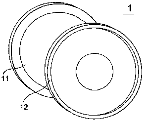
[0002] Traditional drums for cable coils such as figure 1 As shown, by manually pushing the rolling discs on both sides, the drum can be coiled or wired at the rolling position on the ground. On the one hand, it is time-consuming and labor-intensive to push manually. When placed stably on the ground, stones are traditionally used to block both sides of the rolling disc to prevent accidental rolling. Currently, there is no special tool for positioning, which is inconvenient to use

Method used


Image

  • Cable roller coiling device
  • Cable roller coiling device
  • Cable roller coiling device

Examples


Embodiment Construction

[0021] In order to make the object, technical solution and advantages of the present invention clearer, the present invention will be further described in detail below in conjunction with the accompanying drawings and embodiments. It should be understood that the specific embodiments described here are only used to explain the present invention, not to limit the present invention.

[0022] In the description of the present invention, it should be noted that the terms "center", "upper", "lower", "left", "right", "front", "rear", "vertical", "horizontal", The orientation or positional relationship indicated by "inner", "outer", etc. is based on the orientation or positional relationship shown in the drawings, and is only for the convenience of describing the present invention and simplifying the description, rather than indicating or implying that the referred device or element must have Certain orientations, constructed and operative in certain orientations, therefore are not t...


PUM


Abstract

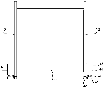
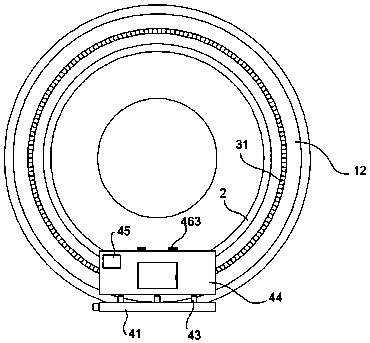
The invention relates to a cable roller coiling device. The cable roller coiling device comprises a coiling roller, wherein the coiling roller comprises a coiling roller body and two rolling discs, and the outer side wall of each of the two rolling discs is fixedly provided with an annular fixing rod; the bottom of each of the two rolling discs is detachably provided with a positioning lifter, each positioning lifter comprises a base, an electric telescopic rod and a lifting box body, an assembling groove corresponding to the corresponding fixing rod is formed in the inner side wall of each lifting box body, and a rotary driving assembly used for driving the coiling roller to rotate is arranged in each lifting box body; and the two ends of the inner side wall of each base are connected topositioning bases correspondingly, the top surface of each positioning base is provided with a positioning surface, and a movable driving device is fixedly arranged on each base and used for driving the two corresponding positioning bases to synchronously move towards each other or away from each other in the length direction of the base. According to the cable roller coiling device, the positioning lifter is designed for the coiling roller, and is used for integrating the limiting function limiting the coiling roller on the ground and the driving and rotating function helping the coiling roller to realize in-situ rotating wire coiling or wire distributing.

Description

technical field [0001] The invention relates to the technical field of cable accessories, in particular to a cable drum reel. Background technique [0002] Traditional drums for cable coils such as figure 1 As shown, by manually pushing the rolling discs on both sides, the drum can be coiled or wired at the rolling position on the ground. On the one hand, it is time-consuming and labor-intensive to push manually. When placed stably on the ground, stones are traditionally used to block both sides of the rolling disc to prevent accidental rolling. At present, there is no special tool for positioning, which is inconvenient to use. Contents of the invention [0003] The technical problem to be solved by the present invention is to provide a cable drum reel, which is convenient to realize the fixed position of the reel drum on the ground, prevent accidental rolling, and also facilitate the rotation of the reel drum in situ by adjustment, so as to facilitate Coil or wire. [...

Claims


Application Information

Patent Timeline
Patent Type & Authority Applications(China)
IPC IPC(8): B65H75/14B65H75/18
CPCB65H75/14B65H75/18B65H2701/53
Inventor 汪浩添
Owner 惠安县创达智能科技有限公司
Why Eureka
Try Eureka