Supercharge Your Innovation With Domain-Expert AI Agents!

Free space duplex communication optical assembly

A free space, optical component technology, applied in free space transmission, electrical components, transmission systems, etc., to achieve the effect of large light emission angle, simple structure and low production cost

Inactive Publication Date: 2019-09-06
HISENSE & JONHON OPTICAL ELECTRICAL TECH CO LTD
View PDF9 Cites 1 Cited by
  • Summary
  • Abstract
  • Description
  • Claims
  • Application Information

AI Technical Summary

Problems solved by technology

[0005] In order to solve the technical problem that both the existing optical fiber communication components and space optical communication components need to be aligned, the present invention proposes a free space duplex communication optical component, which can solve the above problems

Method used


Image

  • Free space duplex communication optical assembly
  • Free space duplex communication optical assembly
  • Free space duplex communication optical assembly

Examples


Embodiment 1

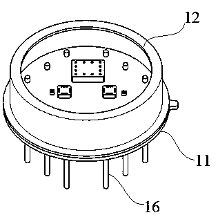
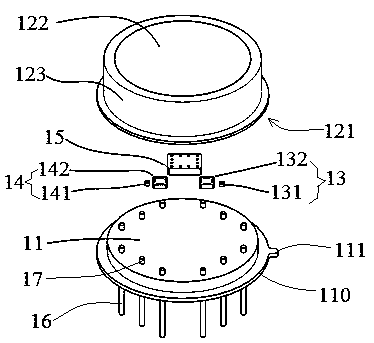
[0027] Embodiment 1, this embodiment proposes a free-space duplex communication optical component, such as figure 1 , figure 2 As shown, including a tube base 11 and a tube cap 12, the upper surface of the tube base 11 is provided with a light receiving assembly 13, a light emitting assembly 14 and a controller 15, and the light receiving assembly 13 and the light emitting assembly 14 are respectively connected to the controller 15 by wires , the tube cap 12 is fastened on the upper surface of the tube base 11, the tube cap 12 has an accommodating cavity 121, the light receiving component 13, the light emitting component 14 and the controller 15 are sealed in the accommodating cavity 121, the top of the tube cap 12 It is a light-transmitting window 122, and the light-transmitting window 122 is made of a light-transmitting sealing material. The receiving surface of the light-receiving component 13 and the emitting surface of the light-emitting component 14 face the light-trans...

Embodiment 2

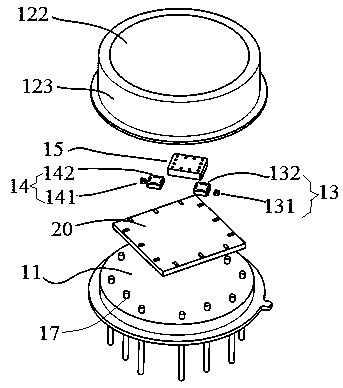
[0039] Embodiment two, such as image 3 As shown, the free space duplex communication optical component of the present embodiment includes a tube base 11 and a tube cap 12, a PCB circuit board 20 is arranged on the upper surface of the tube base 11, and a light receiving component 13, a light emitting Component 14 and controller 15, light-receiving component 13 and light-emitting component 14 are respectively connected with controller 15 by wire, tube cap 12 is fastened on the upper surface of tube base 11, and tube cap 12 has accommodating cavity 121, and light-receiving component 13. The light emitting component 14, the controller 15 and the PCB circuit board 20 are sealed in the accommodating cavity 121, the top of the cap 12 is a light-transmitting window 122, and the light-transmitting window 122 is made of a light-transmitting sealing material, and the light-receiving component 13 The receiving surface of the light-emitting assembly 14 and the emitting surface of the lig...

Embodiment 3

[0041] Embodiment 3, this embodiment proposes another free-space duplex communication optical component with a structural form, such as Figure 4 , Figure 5 As shown, including a PCB circuit board 30 and a cap 12, the upper surface of the PCB circuit board 30 is provided with a light receiving assembly 13, a light emitting assembly 14 and a controller 15, and the light receiving assembly 13 and the light emitting assembly 14 are respectively connected to the PCB circuit board 30 The pads on the upper surface are electrically connected, and the cap 12 is fastened on the upper surface of the PCB circuit board 30. The cap 12 has an accommodating cavity 121, and at least the light receiving component 13, the light emitting component 14 and the controller 15 are sealed in the accommodating cavity 121. Among them, the top of the cap 12 is a light-transmitting window 122 , and the receiving surface of the light-receiving component 13 and the emitting surface of the light-emitting co...


PUM


Abstract

The invention discloses a free space duplex communication optical assembly. The free space duplex communication optical assembly comprises a tube base and a tube cap; a light receiving assembly, a light emitting assembly and a controller are arranged on the upper surface of the tube base. The light receiving assembly and the light emitting assembly are connected with the controller through wires,the tube cap is arranged on the upper surface of the tube base in a buckled mode and provided with a containing cavity; the light receiving assembly, the light emitting assembly and the controller aresealed in the containing cavity; the top of the tube cap is provided with a light transmitting window, and the receiving face of the light receiving assembly and the emitting face of the light emitting assembly face the light transmitting window. According to the free space duplex communication optical assembly, the light receiving assembly, the light emitting assembly and the controller only need to be fixed on the supporting surface; light receiving and emitting signals are emitted out or emitted in through the light-transmitting window, free light receiving and emitting communication of the light signals is achieved, the light emitting angle of the light assembly is large, the light receiving assembly and the light emitting assembly do not need to be matched with various workpieces foralignment operation, the structure is simple, and the manufacturing cost is low.

Description

technical field [0001] The invention relates to an optical communication device, in particular to a free-space duplex communication optical component. Background technique [0002] Traditional optical modules are based on optical fibers for information transmission, which requires wiring of optical fibers, investment in optical fiber costs, and alignment of optical fibers with optical transceiver modules to ensure optical transmission. The structure is complex and the assembly is cumbersome. [0003] In addition, the typical size of the optical antenna used in the traditional space optical communication system is about 300mm*300mm*600mm, and the weight is about 15Kg. Larger in size and weight. And before communication is established, it is necessary to use auxiliary optical systems such as tracking devices, gun sights, or telescopes to debug the optical path. The required auxiliary optical system is large in size and takes a long time to debug, which takes about tens of min...

Claims


Application Information

Patent Timeline
Patent Type & Authority Applications(China)
IPC IPC(8): H04B10/112H04B10/40H04B10/50H04B10/60
CPCH04B10/1123H04B10/40H04B10/50H04B10/60
Inventor 曲业飞张洪涛姜瑜斐武玉谦王晨阳
Owner HISENSE & JONHON OPTICAL ELECTRICAL TECH CO LTD
Features
  • R&D
  • Intellectual Property
  • Life Sciences
  • Materials
  • Tech Scout
  • Unparalleled Data Quality
  • Higher Quality Content
  • 60% Fewer Hallucinations
Learn More