Light reflecting component and laser marking module

A reflective element and laser marking technology, which is applied to reflective reflectors, active optical measuring devices, measuring devices, etc., can solve the problems of inconvenient carrying by construction workers

Pending Publication Date: 2019-09-10
QINGDAO LASENCE
View PDF0 Cites 3 Cited by
  • Summary
  • Abstract
  • Description
  • Claims
  • Application Information

AI Technical Summary

Problems solved by technology

[0004] The purpose of the present invention is to provide a reflective element and a laser marking module to alleviate the existing technical problems that t

Method used


Image

  • Light reflecting component and laser marking module
  • Light reflecting component and laser marking module
  • Light reflecting component and laser marking module

Examples


Embodiment 1

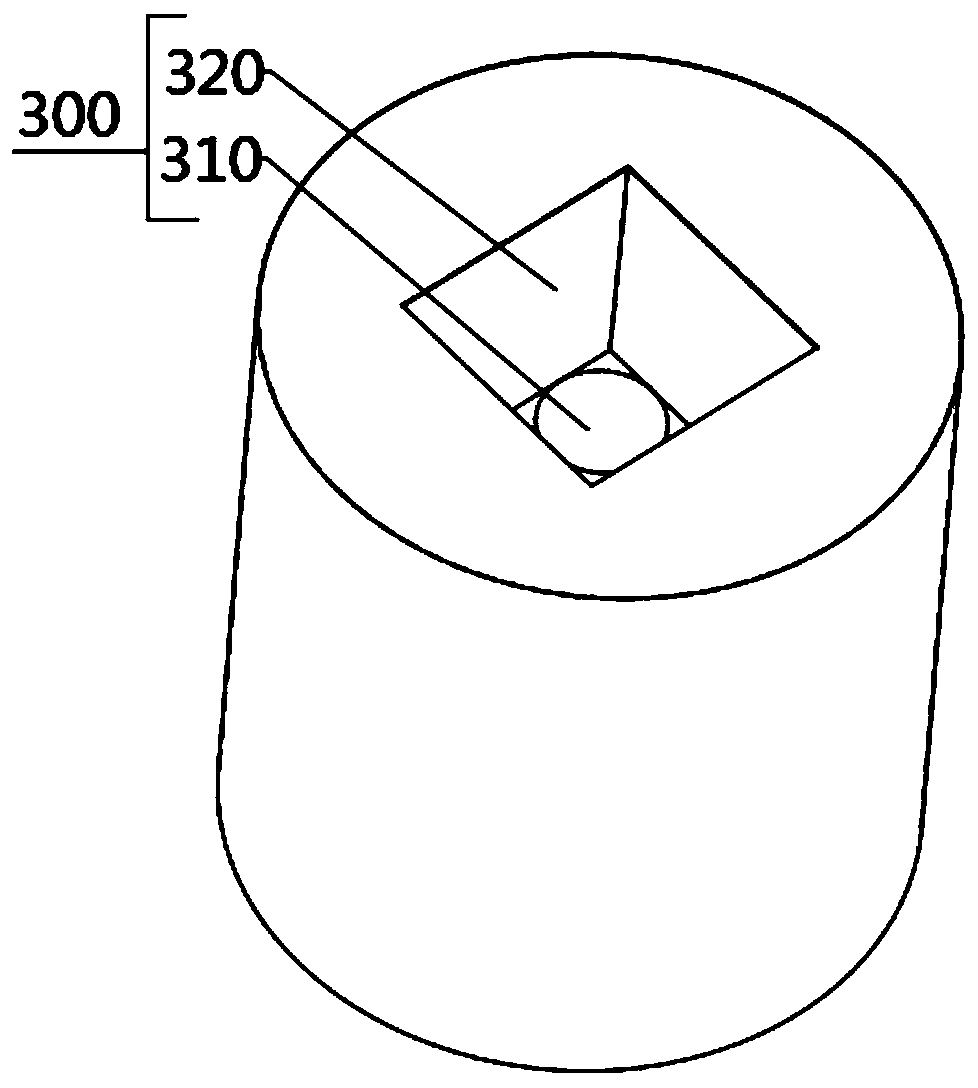
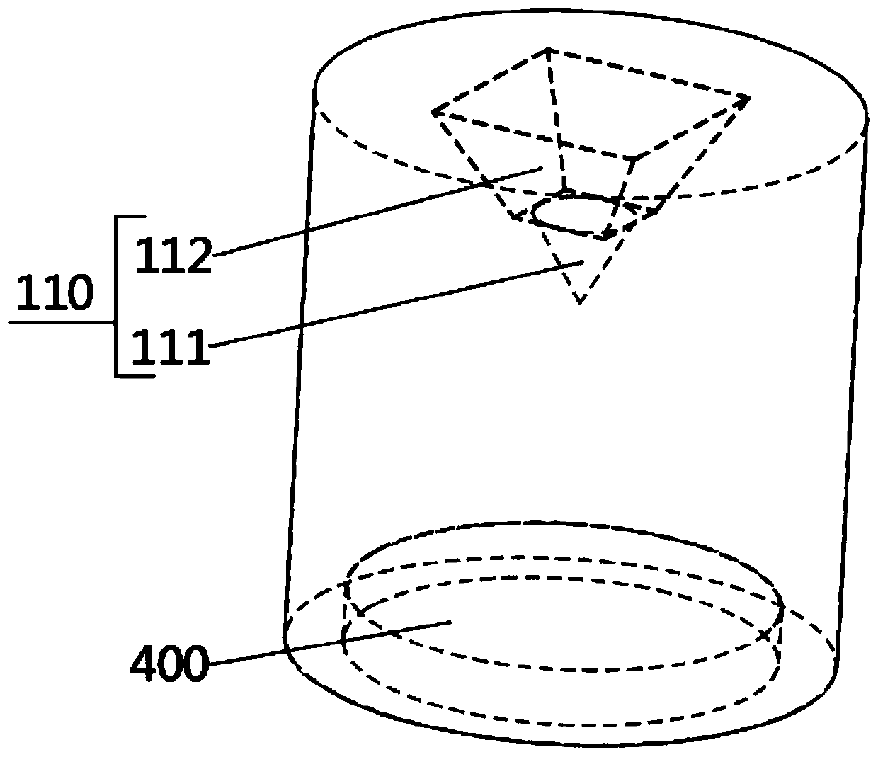
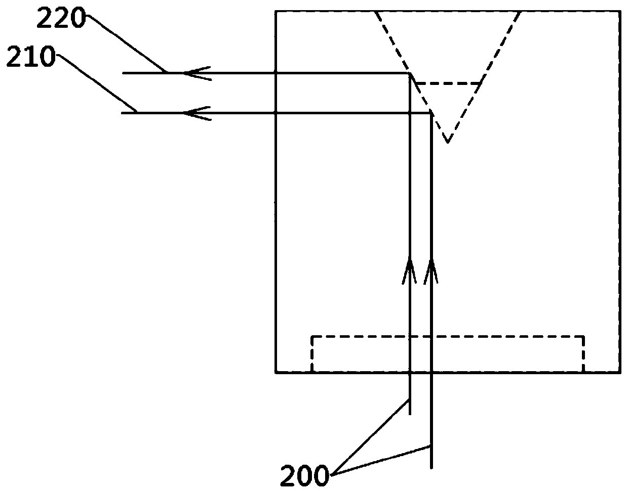
[0034] like Figure 1-Figure 4 As shown, the embodiment of the present invention provides a reflective element 100, the reflective element 100 includes a reflective part 110, when the incident light 200 is irradiated on the reflective part 110, the reflective part 110 can reflect the incident light 200 in the circumferential direction . The reflection part 110 includes a reflection cone surface 111 and a reflection plane 112, the reflection cone surface 111 and the reflection plane 112 are sequentially arranged along the axis direction of the reflection cone surface 111, when the incident light 200 is along the reflection cone surface 111 When the axis direction is incident, and part of the reflected light can be irradiated on the reflective cone surface 111, the reflective cone surface 111 can form a ring-shaped linear light 210 in the circumferential direction of the reflective element 100, and the linear light 210 projects A straight line is formed on the wall; part of the...

Embodiment 2

[0045] like Figure 5 and Image 6 As shown, the difference from Embodiment 1 lies in the shape of the reflective element 100, the reflective part 110 is formed by a protruding structure, the reflective element 100 includes a conical structure 500, and the conical structure 500 includes a cone tip and a bottom Side, the outer wall of the cone is provided with a third recess 510, the bottom surface of the third recess 510 is a plane; there is a distance between the third recess 510 and the tip of the cone, and the bottom surface of the third recess 510 forms the The reflection plane 112 , the conical surface between the third concave portion 510 and the cone tip forms the reflection cone surface 111 . That is to say, when the incident light 200 irradiates on the reflective element 100 , it first contacts the reflective tapered surface 111 of the tapered tip, and then contacts the reflective plane 112 formed by the bottom surface of the third recess 510 above it. When the prop...


PUM

PropertyMeasurementUnit
Cone angleaaaaaaaaaa

Abstract

The invention provides a light reflecting component and a laser marking module, and relates to the technical field of laser marking modules. The light reflecting component comprises a reflecting part;the reflecting part is used for reflecting incident light circumferentially; the reflecting part comprises a reflecting conical surface and a reflecting plane; the reflecting conical surface and thereflecting plane are sequentially arranged along the axis direction of the reflecting conical surface; the reflecting conical surface is used for forming linear light in the circumferential directionof the light reflecting component; and the reflecting plane is used for forming dot light in the circumferential direction of the light reflecting component. By means of an optical component, a beam of incident light can form 360-DEG annular light and dot light at the same time; the dot light plays an indication role for 360-DEG annular light; when the laser marking module with the light reflecting component rotates horizontally, the 360-DEG annular light is not changed; the dot light can horizontally move; and thus, the dynamic indication effect is achieved.

Description

technical field [0001] The invention relates to the technical field of laser marking modules, in particular to a reflective element and a laser marking module. Background technique [0002] The laser marking module is widely used in construction projects, and it has both the functions of the original level and theodolite marking. At present, a conical reflector is used to project a laser beam onto the conical reflector to form a circular laser surface, which is projected into space to form a 360° laser line. Compared with the commonly used three to four linear laser light sources to form a 360° laser line, this line projection method has the characteristics of low cost, low energy consumption, compact structure, and good uniformity of laser lines. In the application of instrument products, it has a relatively good advantage. [0003] However, in engineering applications, construction personnel can first use the 360° laser line to mark the space to form a straight marking l...

Claims


Application Information

Patent Timeline
IPC IPC(8): G01C15/00G02B5/12
CPCG01C15/002G02B5/12
Inventor 孙国文
Owner QINGDAO LASENCE
Why Eureka
Try Eureka