An unmanned aerial vehicle with a gliding function

A kind of unmanned aerial vehicle, functional technology, applied in the field of unmanned aerial vehicles, can solve problems such as motor control difficulties, battery abnormalities, etc.

Inactive Publication Date: 2019-09-13
株式会社种子型工程
View PDF2 Cites 2 Cited by
  • Summary
  • Abstract
  • Description
  • Claims
  • Application Information

AI Technical Summary

Problems solved by technology

In drones, there are cases where control becomes diffic

Method used


Image

  • An unmanned aerial vehicle with a gliding function
  • An unmanned aerial vehicle with a gliding function
  • An unmanned aerial vehicle with a gliding function

Examples


Embodiment approach 1

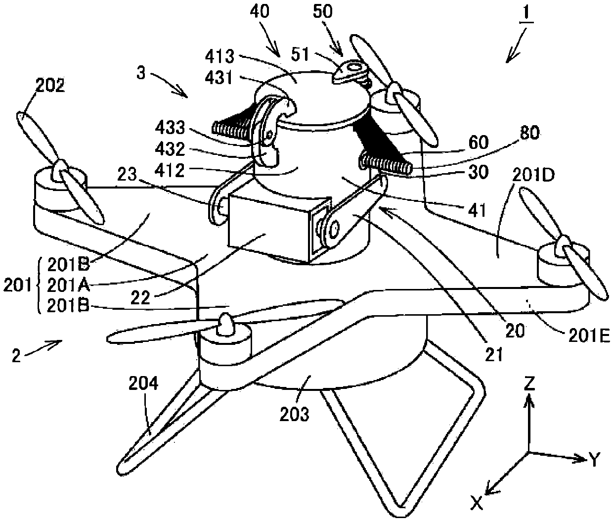
[0040] refer to figure 1 , the drone 1 with the gliding function of Embodiment 1 includes the drone main body 2 and the paragliding device 3 . The drone body 2 includes an upper frame 201 , a plurality (more specifically, four) of rotors 202 , a base portion 203 and a leg portion 204 .

[0041] The upper chassis 201 has a flat plate shape. The upper frame 201 has a shape in which a plurality of (more specifically, four) arm portions 201B protrude from a central portion 201A when viewed from the side of the first main surface 201D as one main surface. The arm portions 201B are arranged at equal intervals (evenly) in the circumferential direction of the upper frame 201 when viewed from the first principal surface 201D side. The width of each arm portion 201B becomes smaller as it moves away from the central portion 201A.

[0042] The respective rotors 202 are arranged at the front ends of the arms 201B of the upper frame 201 . Each rotor 202 is arranged on the first main sur...

Embodiment approach 2

[0073] Next, Embodiment 2 which is another embodiment of the present invention will be described. The drone 1 with a gliding function according to the second embodiment basically has the same structure as that of the first embodiment. However, in Embodiment 2, the structure of the accommodation part 40 of the paraglider apparatus 3, the steering part 20, and the parachute opening device 50 is different from the case of Embodiment 1. Hereinafter, points different from the case of Embodiment 1 will be described.

[0074] refer to Figure 8 and Figure 9 , the drone 1 with the gliding function of Embodiment 2 includes the drone main body 2 and the paragliding device 3 .

[0075] The drone main body 2 includes an upper frame 201 , a plurality (more specifically, four) of rotors 202 and a base portion 203 .

[0076] The upper chassis 201 has a flat plate shape. The upper frame 201 has a shape in which four arm portions 201B protrude from the central portion 201A when viewed fr...


PUM


Abstract

The invention aims to provide an unmanned aerial vehicle with a gliding function. The unmanned aerial vehicle enables selection of a landing point when the control of the unmanned aerial vehicle has problems. The unmanned aerial vehicle 1 with the gliding function includes an unmanned aerial vehicle main body (2) and a paraglider device (3) arranged on the unmanned aerial vehicle main body (2). The paraglider device (3) includes a canopy (10), a helm portion(20), a brake cord (30) that connects the canopy (10) and the helm portion (20), a housing portion (40) that holds the canopy (10) in a state in which the canopy (10) is closed, and a canopy opening device for releasing the canopy (10) and opening the canopy (10). The helm portion (20) controls the canopy (10) via the brake rope (30) while the canopy (10) is opened, thereby causing the unmanned aerial vehicle to glide.

Description

technical field [0001] The invention relates to an unmanned aerial vehicle with a gliding function. Background technique [0002] Unmanned aerial vehicles such as multirotors and radio-controlled helicopters are known. In recent years, the miniaturization and high performance of unmanned aerial vehicles have been rapidly developed, and unmanned aerial vehicles have been used for various purposes. In drones, there are cases where control becomes difficult due to battery abnormality, motor abnormality, and the like. [0003] Currently, there is proposed an unmanned aerial vehicle including a parachute for emergency landing of the unmanned aerial vehicle when the control of the unmanned aerial vehicle fails (for example, refer to Patent Document 1 and Patent Document 2). [0004] prior art literature [0005] patent documents [0006] Patent Document 1: Japanese Patent Laid-Open No. 2016-88110 [0007] Patent Document 2: Japanese Patent Laid-Open No. 2016-88111 Contents ...

Claims


Application Information

Patent Timeline
IPC IPC(8): B64C31/036
CPCB64C31/036
Inventor 大高悦裕田村博
Owner 株式会社种子型工程
Why Eureka
Try Eureka