Image forming device

A technology in images and devices, applied in the field of detection accuracy of torque values, to achieve the effect of preventing torque fluctuations

Active Publication Date: 2019-09-13
KONICA MINOLTA INC
View PDF20 Cites 0 Cited by
  • Summary
  • Abstract
  • Description
  • Claims
  • Application Information

AI Technical Summary

Problems solved by technology

[0011] The same problem occurs when using a method other than the fixing pad method to predict the life of the fixing device based on the torque value.

Method used


Image

  • Image forming device
  • Image forming device
  • Image forming device

Examples


Embodiment Construction

[0048] Hereinafter, embodiments of the image forming apparatus according to the present invention will be described with reference to the drawings.

[0049] [1] Structure of image forming apparatus

[0050] First, the configuration of the image forming apparatus according to the present embodiment will be described.

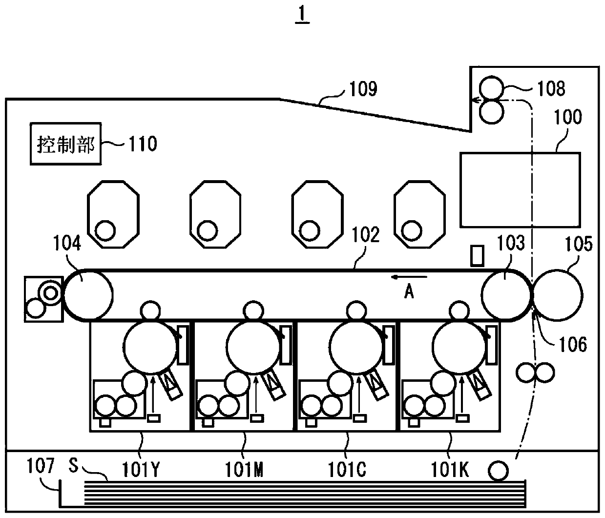
[0051] like figure 1 As shown, the image forming apparatus 1 is a so-called tandem color printer, and uses image forming units 101Y, 101M, 101C, and 101K to form toner images of YMCK colors. The formed toner images are sequentially electrostatically transferred onto the outer peripheral surface of the intermediate transfer belt 102 so as to overlap each other, thereby forming color toner images. The intermediate transfer belt 102 is an endless belt, and travels rotationally in the direction of arrow A in a state where the driven roller 103 and the driven roller 104 are spanned.

[0052] The intermediate transfer belt 102 is sandwiched between the secondary tr...


PUM


Abstract

The invention provides an image forming device that is capable of accurately detecting the abrasion state of a fixing pad. An electrophotographic image forming device executes warm-up for raising a temperature of a fixing rotating body prior to execution of a print job. During warm-up, the fixing rotating body is rotated at a constant speed in order to prevent temperature unevenness. After the fixing rotary body has reached the target temperature, the temperature of the fixing rotary body is controlled so as to be substantially constant during a period of time until the first recording sheet reaches the fixing rotary body. Further, since there is no change in the drive speed due to the entry of the recording sheet, detection accuracy of the torque can be improved by detecting the torque ofthe motor that rotationally drives the fixing rotating body within the period. Therefore, it is possible to improve the prediction accuracy of the life of the fixing device using the torque value.

Description

technical field [0001] The present invention relates to an image forming apparatus, and in particular, to a technique for improving the detection accuracy of a torque value used for life determination of a fixing device. Background technique [0002] An electrophotographic image forming apparatus includes a fixing device that fixes a toner image on a recording sheet by pressing the heat-fused toner image against the recording sheet. There are various fixing methods for fixing devices. For example, a fixing pad-type fixing device performs a fixing process by passing a recording sheet through a fixing nip formed by pressing a pressure roller against a fixing pad. Since the heat capacity of the fixing pad is smaller than the heat capacity of the roller, the use of the fixing pad system can achieve energy saving compared to the case where the fixing nip is formed by press-contacting the roller pair. [0003] In the fixing pad system, in order to improve the conveyance of the re...

Claims


Application Information

Patent Timeline
Patent Type & Authority Applications(China)
IPC IPC(8): G03G15/20G03G15/00
CPCG03G15/2039G03G15/55G03G15/205G03G15/553G03G2215/2045
Inventor 田中敏明渡边政行福永雅行山本峰生
Owner KONICA MINOLTA INC
Why Eureka
Try Eureka