Travel route generation device, travel route generation method, and vehicle control device

A technology for driving paths and generating devices, applied in control devices, vehicle components, transportation and packaging, etc., can solve problems such as the reduction of prediction accuracy, and achieve the effect of preventing the reduction of prediction accuracy.

Pending Publication Date: 2021-11-09
MITSUBISHI ELECTRIC CORP
View PDF1 Cites 0 Cited by
  • Summary
  • Abstract
  • Description
  • Claims
  • Application Information

AI Technical Summary

Problems solved by technology

However, in the case of long-term prediction, since the motion state has changed from the current motion state, the prediction accuracy will decrease

Method used


Image

  • Travel route generation device, travel route generation method, and vehicle control device
  • Travel route generation device, travel route generation method, and vehicle control device
  • Travel route generation device, travel route generation method, and vehicle control device

Examples


Embodiment approach 1

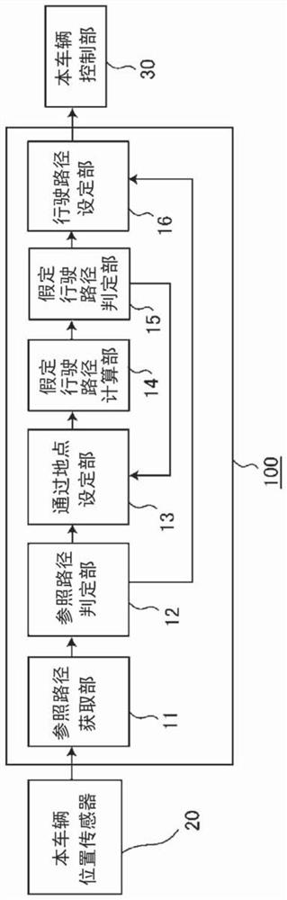
[0030] figure 1 It is a block diagram illustrating the configuration of the travel route generation device according to the first embodiment.

[0031] figure 1 Among them, the driving route generation device 100 acquires the position and orientation (direction) of the own vehicle from the own vehicle position sensor 20 (such as GPS and geomagnetic sensor) mounted on the own vehicle, and generates the driving route of the own vehicle by the following method. The generated data is output to the vehicle control unit 30 . Then, the host vehicle control unit 30 controls the host vehicle so as to travel on the travel route of the host vehicle generated by the travel route generation device 100 .

[0032] The travel route generation device 100 includes a reference route acquisition unit 11 , a reference route determination unit 12 , a passing point setting unit 13 , a provisional travel route calculation unit 14 , a provisional travel route determination unit 15 , and a travel rout...

Embodiment approach 2

[0056] Next, a travel route generation device according to Embodiment 2 will be described. Image 6 It is a block diagram illustrating the configuration of the travel route generation device according to the second embodiment.

[0057] figure 2 Herein, the travel route generation device 200 acquires the position and orientation (direction) of the host vehicle from the host vehicle position sensor 20 (for example, GPS and geomagnetic sensor) mounted on the host vehicle. In addition, the position and orientation (direction) of other vehicles existing around the own vehicle are acquired using the other vehicle position sensor 40 (for example, a millimeter-wave radar or a camera) mounted on the own vehicle with the own vehicle's position as the origin. Then, the travel route of the other vehicle is generated by the following method, and the generated data is output to the vehicle travel route calculation unit 50 . The own-vehicle travel route calculation unit 50 calculates the ...

Embodiment approach 3

[0084] Next, a travel route generation device according to Embodiment 3 will be described. Figure 8 It is a block diagram illustrating the configuration of the travel route generation device according to the third embodiment.

[0085] Figure 8 Among them, the travel route generation device 300 acquires the position and orientation (direction) of the host vehicle from the host vehicle position sensor 20 (for example, GPS and geomagnetic sensor) mounted on the host vehicle. In addition, the position and orientation (direction) of other vehicles existing around the own vehicle are acquired using the other vehicle position sensor 40 (for example, a millimeter-wave radar or a camera) mounted on the own vehicle with the own vehicle's position as the origin. Then, the traveling route of the host vehicle is generated by the following method, and the generated data is output to the host vehicle control unit 30 . Then, the host vehicle is controlled based on the travel route generat...


PUM


Abstract

The present invention involves: a vehicle position sensor (20) that detects the position of a vehicle; a reference route acquisition unit (11) that acquires a reference route for the vehicle to travel on; a reference route determination unit (12) that determines whether or not the vehicle is traveling on the reference route; a temporary travel route calculation unit (14) that, if it is determined by the reference route determination unit (12) that the vehicle is not traveling on the reference route, calculates a temporary travel route from at least two points comprising the travel start point of the vehicle and the end point of the reference route; and a travel route setting unit that sets, as a route for the vehicle to travel on, either the temporary travel route calculated by the temporary travel route calculation unit (14) or the reference route where it has been determined by the reference route determination unit (12) that the vehicle is traveling.

Description

technical field [0001] The present application relates to a driving route generating device, a driving route generating method, and a vehicle control device. Background technique [0002] As a method of predicting the traveling route of a vehicle, there are predictions using motion models, predictions using road shapes (maps), and the like. In the former prediction using a motion model, a specific motion model is used to predict the travel path of the vehicle based on the motion state of the target, such as the speed and acceleration observed and estimated by the sensor. In this method, the motion state of the estimated target is highly accurate, and the accuracy is high in very short-term predictions such as 1 second or less. However, in the case of long-term prediction, since the motion state changes from the current motion state, the prediction accuracy decreases. [0003] In the latter prediction using the road shape, for example, as disclosed in Patent Document 1, the...

Claims


Application Information

Patent Timeline
IPC IPC(8): B60W30/10B60W30/095G08G1/16
CPCG01C21/34B60W30/0956B60W2554/4041
Inventor 饭田公司
Owner MITSUBISHI ELECTRIC CORP
Why Eureka
Try Eureka