Connection terminal for PCB

A technology of PCB board and connection terminal, applied in the direction of connection, fixed connection, contact parts, etc., can solve the problem that the PCB board cannot realize detachable connection, etc., and achieve the effect of quick electrical connection and simple operation

Pending Publication Date: 2019-09-13
XIAMEN GUANG WANG IND
View PDF0 Cites 0 Cited by
  • Summary
  • Abstract
  • Description
  • Claims
  • Application Information

AI Technical Summary

Problems solved by technology

[0004] The invention provides a connection terminal for PCB boards, aiming to improve the problem that the connection between PCB boards cannot realize detachable connection in the prior art

Method used


Image

  • Connection terminal for PCB
  • Connection terminal for PCB
  • Connection terminal for PCB

Examples


no. 1 example

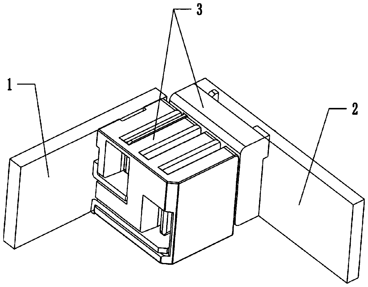
[0045] The angle between the first PCB board 1 and the second PCB board 2 is 90°, as follows:

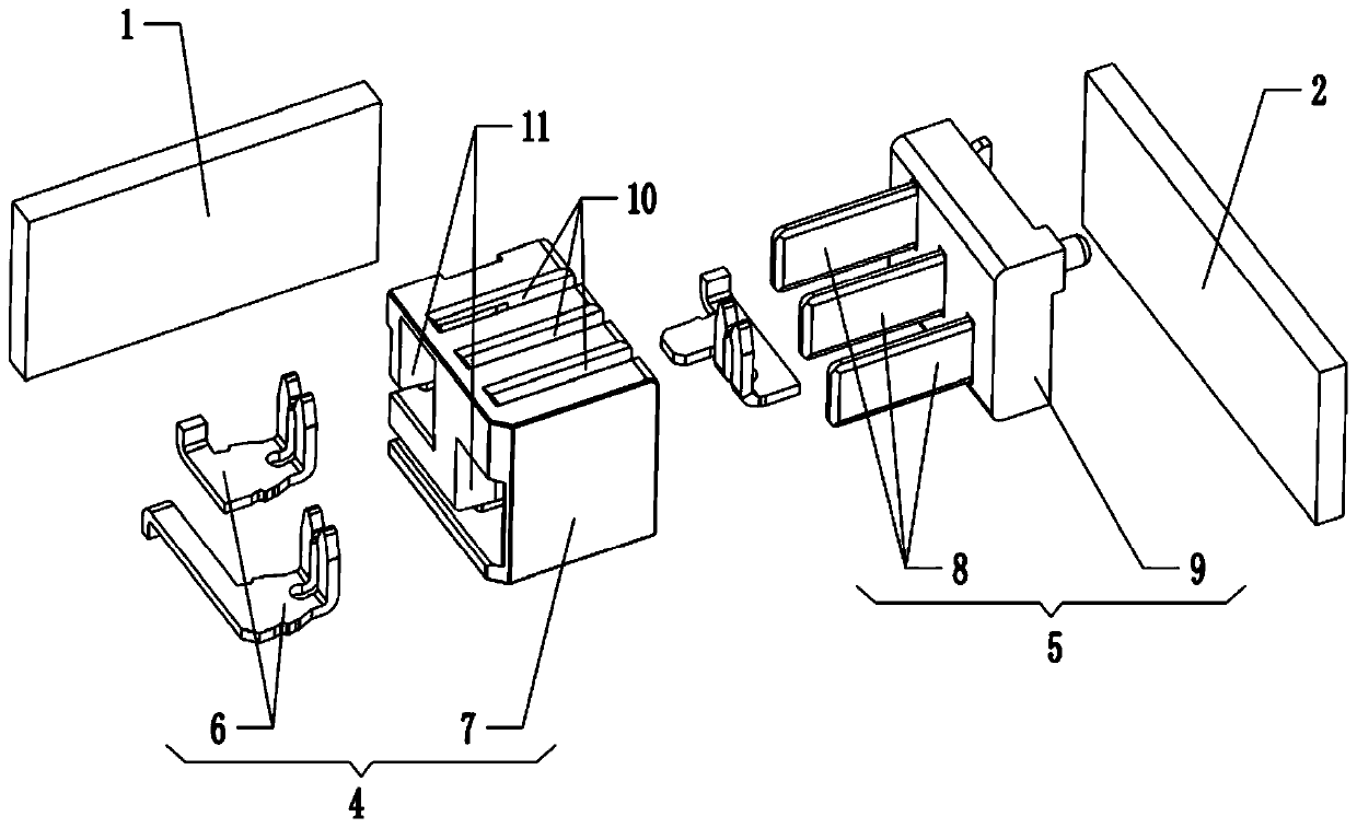
[0046] Depend on Figure 1 to Figure 6 As shown, in this embodiment, a connection terminal for a PCB board is used to electrically connect the first PCB board 1 and the second PCB board 2, and the connection terminal 3 includes:

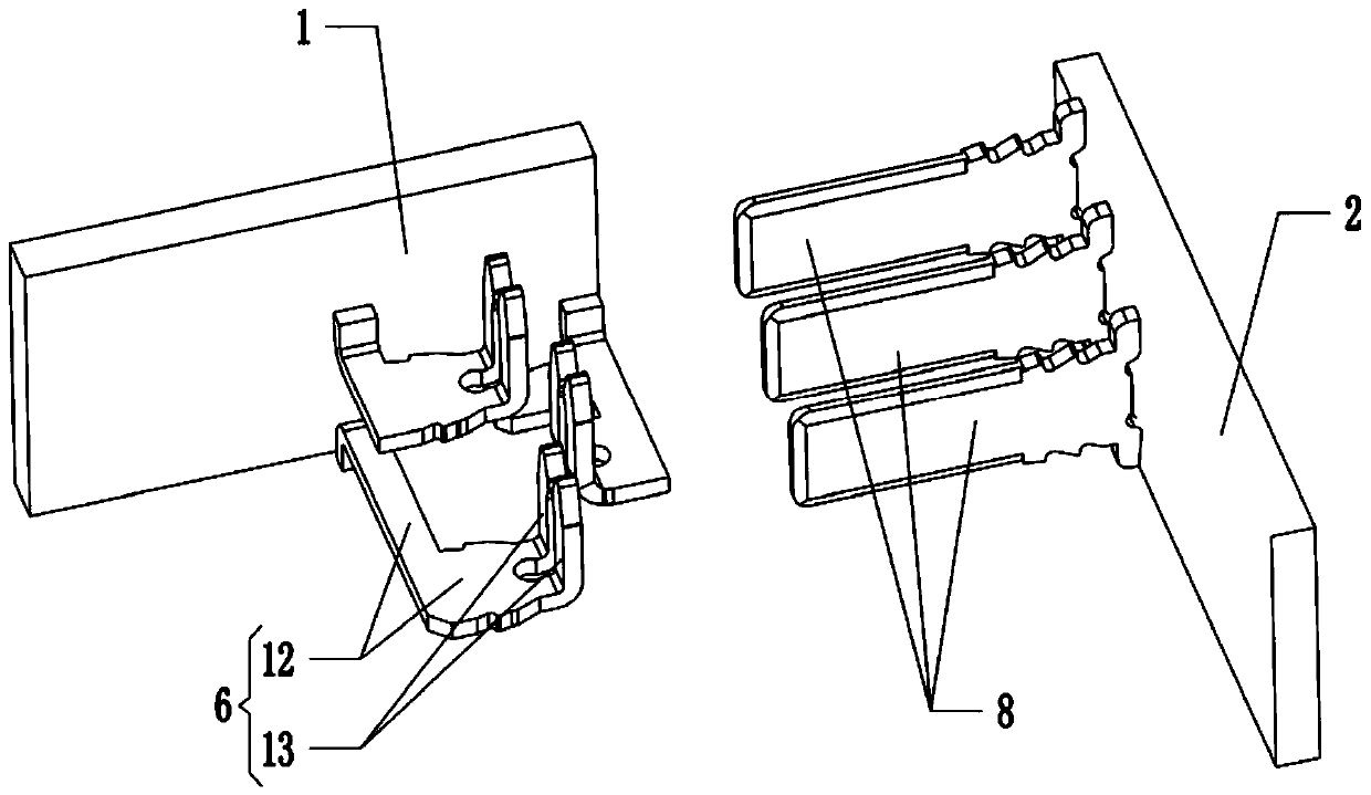
[0047] Female header assembly 4, which includes a female header housing 7 provided with a slot 10, and a conductive clip 6 configured on the female header housing 7 and supported on the first PCB board 1; the conductive clip 6 has a socket 10 The clamping section 13, and the connecting section 12 configured on the clamping section 13 and electrically connected to the first PCB board 1;

[0048] Male head assembly 5, which includes a male head housing 9 configured on the second PCB board 2, and a male plug 8 configured on the male head housing 9 and electrically connected to the second PCB board 2, the male plug 8 and the clamping section 13 matching;

...

no. 2 example

[0055] The angle between the first PCB board 1 and the second PCB board 2 is 90°, as follows:

[0056] Depend on Figure 8 to Figure 11 As shown, in this embodiment, the clamping section 13 is parallel to the connecting section 12 , and both the clamping section 13 and the connecting section 12 are disposed in the slot 10 . That is to say: in this embodiment, the female housing 7 is not provided with an accommodating groove 11, the clamping section 13 and the connecting section 12 are both arranged in the slot 10, and the end of the connecting section 12 is welded to the first PCB board 1 superior.

[0057] Depend on Figure 7 , Figure 8 and Figure 9 As shown, in this embodiment, the first PCB board 1 and the second PCB board 2 also form a 90° angle. In this embodiment, the other structures of the female component 4 and the male component 5 are the same as those of the first embodiment, and will not be repeated here.

no. 3 example

[0059] The angle between the first PCB board 1 and the second PCB board 2 is 180°, as follows:

[0060] Depend on Figure 12 to Figure 15 As shown, in this embodiment, the first PCB board 1 and the second PCB board 2 are at 180°, specifically, the female header assembly 4 is arranged on the first PCB board 1, and the male header assembly 5 is arranged on the second PCB board 2 on. The second PCB board 2 can drive the male assembly 5 and the female assembly 4 on the first PCB 1 to achieve detachable electrical connection.

[0061] In this embodiment, the structures of the female component 4 and the male component 5 are the same as those of the first embodiment, and will not be repeated here.


PUM


Abstract

The invention provides a connection terminal for a PCB, and relates to the technical field of connection terminals. The connection terminal is used for electrically connecting a first PCB and a secondPCB, particularly, the connection terminal comprises a female head assembly and a male head assembly, wherein the female head assembly comprises a female head shell and a conductive clamp, the femalehead shell is provided with a slot, the conductive clamp is arranged at the female head shell and is supported at the first PCB, the conductive clamp is provided with a clamping segment and a connection segment, the clamping segment is accommodated in the slot, the connection segment is arranged at the clamping segment and is electrically connected to the first PCB, the male head assembly comprises a male head shell and a male plug, the male head shell is arranged at the second PCB, the male plug is arranged at the male head shell and is electrically connected to the second PCB, the male headassembly can be driven to be arranged at the female head assembly by the second PCB so that the male plug is arranged at the clamping segment and electrical connection of the first PCB and the secondPCB is achieved, and the male head assembly can be driven to be separated from the female head assembly by the second PCB so that the male plug is separated from the clamping segment and connection of the first PCB and the second PCB is broken.

Description

technical field [0001] The present invention relates to the technical field of connection terminals, in particular to a connection terminal for a PCB board. Background technique [0002] Some electronic products have multiple PCB boards, and these PCB boards need to be electrically connected. In the prior art, the PCB boards are usually connected by wires or directly welded together. However, this will result in that the PCB boards cannot be detachable, and the connection operation between the PCB boards is too cumbersome and complicated to realize fast electrical connection. [0003] In view of this, the inventor proposes the present application after studying the prior art. Contents of the invention [0004] The invention provides a connection terminal for PCB boards, aiming to improve the problem in the prior art that the connection between PCB boards cannot realize detachable connection. [0005] In order to solve the above-mentioned technical problems, the present ...

Claims


Application Information

Patent Timeline
Patent Type & Authority Applications(China)
IPC IPC(8): H01R12/72H01R12/73H01R13/10H01R13/04H01R13/46H01R12/57
CPCH01R12/57H01R12/722H01R12/732H01R12/737H01R13/04H01R13/10H01R13/46H01R12/721H01R12/73
Inventor 陈炳水
Owner XIAMEN GUANG WANG IND
Why Eureka
Try Eureka