

scroll compressor
A technology of scroll compressors and scroll parts, which is applied in the direction of rotary piston machines, rotary piston pumps, mechanical equipment, etc., and can solve problems such as reduced operating capacity
- Summary
- Abstract
- Description
- Claims
- Application Information
AI Technical Summary
Problems solved by technology
Method used
Image

Examples
Embodiment approach 1
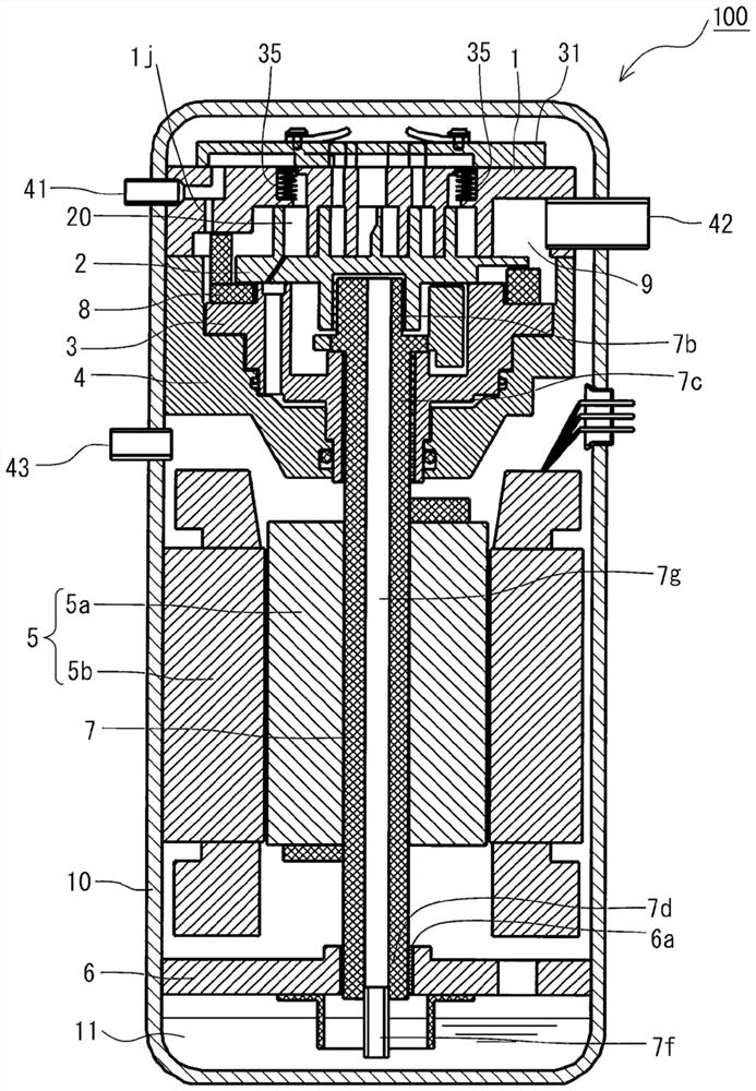
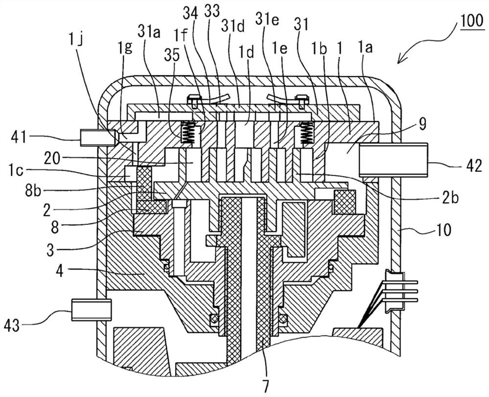
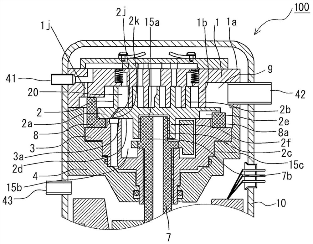
[0021] figure 1 It is a longitudinal sectional view showing the overall structure of the scroll compressor according to Embodiment 1 of the present invention. Figure 2 ~ Figure 4 It is an enlarged longitudinal sectional view showing the upper part of the scroll compressor according to Embodiment 1 of the present invention, and all show the same parts. figure 2 It is a figure explaining the fixed scroll 1 especially. image 3 It is a figure explaining the orbiting scroll 2 especially. Figure 4 It is a figure explaining especially the compliant frame (Compliant frame) 3 and the guide frame 4.
[0022] First, the overall structure of the scroll compressor 100 will be described. Such as figure 1 As shown, a scroll compressor 100 accommodates a fixed scroll 1, an oscillating scroll 2, a flexible frame 3, a guide frame 4, a motor 5, an auxiliary frame 6, a shaft 7, and an Oldham slider mechanism in a closed container 10. (Oldham mechanism)8. Among them, the fixed scroll 1 a...
Embodiment approach 2
[0076] Next, based on Figure 8 Scroll compressor 101 according to Embodiment 2 of the present invention will be described. Figure 8 It is a vertical cross-sectional view showing an enlarged upper portion of a scroll compressor according to Embodiment 2 of the present invention. However, the same reference numerals are assigned to the same configurations as those of the scroll compressor 100 described in Embodiment 1, and description thereof will be appropriately omitted.
[0077] The scroll compressor 101 according to Embodiment 2 differs from the above-described configuration of Embodiment 1 in that the injection check valve mechanism 36 that prevents the refrigerant in the compression chamber 20 from flowing back into the injection circuit is provided. Specifically, on the fixed base plate 1a of the fixed scroll 1, at the halfway position from the side portion corresponding to the thickness of the plate toward the upper portion of the inflow hole 1g, there is formed a jet...
Embodiment approach 3
[0082] Next, based on Figure 9 and Figure 10 Scroll compressor 102 according to Embodiment 3 of the present invention will be described. Figure 9 It is a vertical cross-sectional view showing an enlarged upper portion of a scroll compressor according to Embodiment 3 of the present invention. Figure 10 It is an explanatory diagram showing a scroll compressor according to Embodiment 3 of the present invention, and shows in a planar manner that the protrusion of the swing table is displaced relative to the suction communication hole as the swing scroll rotates. Illustrating. However, the same reference numerals are assigned to the same configurations as those of the scroll compressors described in Embodiments 1 and 2, and description thereof will be appropriately omitted. In addition, in Figure 9 In the scroll compressor 102 according to the third embodiment shown, the structure in which the injection check valve mechanism 36 described in the above-mentioned second embod...
PUM
 Abstract
Description
Claims
Application Information