Coil component

A technology of coil parts and components, applied in the direction of transformer/inductor parts, electrical components, transformer/inductor coils/windings/connections, etc.

Pending Publication Date: 2019-09-24
MURATA MFG CO LTD
View PDF4 Cites 0 Cited by
  • Summary
  • Abstract
  • Description
  • Claims
  • Application Information

AI Technical Summary

Problems solved by technology

At this time, there is a problem that the stray capacitance generated between the turns of the wire rod in the portion where the adjacent turns of the wire rod are in close contact with each other depends on the physical properties of the coating agent and the method of adhesion to the wire rod. Significant increases or decreases, especially fluctuations in the high-frequency characteristics that are important in the coil components of the signal system

Method used


Image

  • Coil component
  • Coil component
  • Coil component

Examples


Embodiment Construction

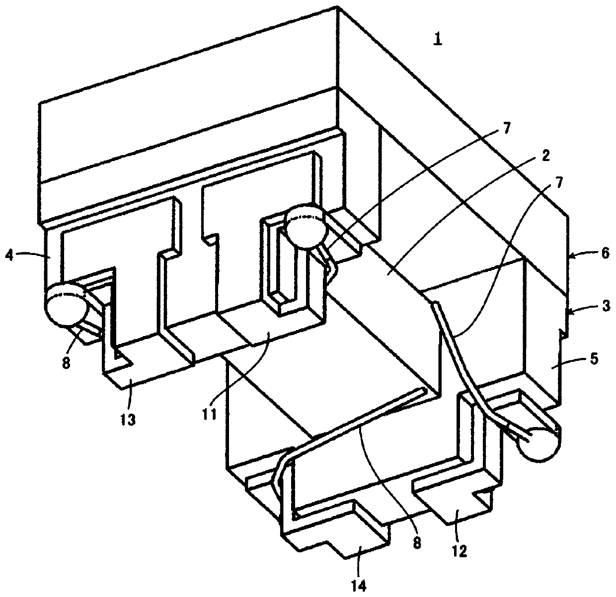
[0028] refer to figure 1 as well as figure 2 , the coil component 1 according to the first embodiment of the present invention will be described. The coil component 1 constitutes, for example, a common mode choke coil.

[0029] The coil component 1 includes a drum-shaped iron core 3 having a winding core portion 2 . The drum core 3 includes first and second flange portions 4 and 5 respectively provided at first and second end portions opposite to each other of the winding core portion 2 . The coil component 1 may further include a plate-like core 6 spanning between the first and second flange portions 4 and 5 . The drum core 3 and the plate core 6 are made of a non-conductive material, for example, a non-magnetic material such as alumina, a magnetic material such as ferrite, or resin.

[0030] The aforementioned plate-like core 6 is bonded to the first and second flange portions 4 and 5 with an adhesive. Curable resins such as epoxy resins can be used as the binder. Her...


PUM

PropertyMeasurementUnit
melting pointaaaaaaaaaa
relative permittivityaaaaaaaaaa

Abstract

The present disclosure provides a coil component in which the coating material is unlikely to flow into the portions of the wire that are in close contact with each other. The coil component (1) includes a blocking component (15) that contains a resin and that blocks a route that leads to a gap between turns of a wire from an outside at portions of the wire (7,8) that are in close contact with each other between adjoining turns.

Description

technical field [0001] The present invention relates to a coil component, and more particularly to a coil component including at least one wire material that is helically wound a plurality of turns and has a portion that is in close contact with each other between adjacent turns. Background technique [0002] As a conventional coil component, for example, there is a component described in JP 2017-22372 A (Patent Document 1). In order to obtain this coil component, a wire rod having a three-layer structure of a core material, a cover film, and a resin film is wound spirally around the winding core for several turns, and then the resin film is melted by heat treatment, thereby forming a layer that penetrates to the wound area. Each process of resin covering the gap between the wire rods. In this manner, in Patent Document 1, a structure in which the wire rod is covered with the resin coating layer is obtained. According to the description of Patent Document 1, it is possible...

Claims


Application Information

Patent Timeline
Patent Type & Authority Applications(China)
IPC IPC(8): H01F27/28H01F27/30
CPCH01F27/28H01F27/303H01F27/2823H01F27/323H01F27/292H01F17/045H01F3/10
Inventor 五十岚启雄五十岚勇治
Owner MURATA MFG CO LTD
Why Eureka
Try Eureka